Electronic apparatus with display unit, information-processing method, and computer product

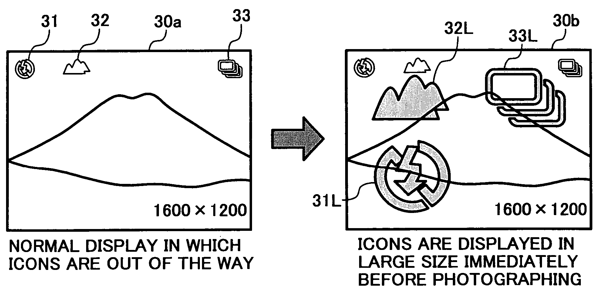
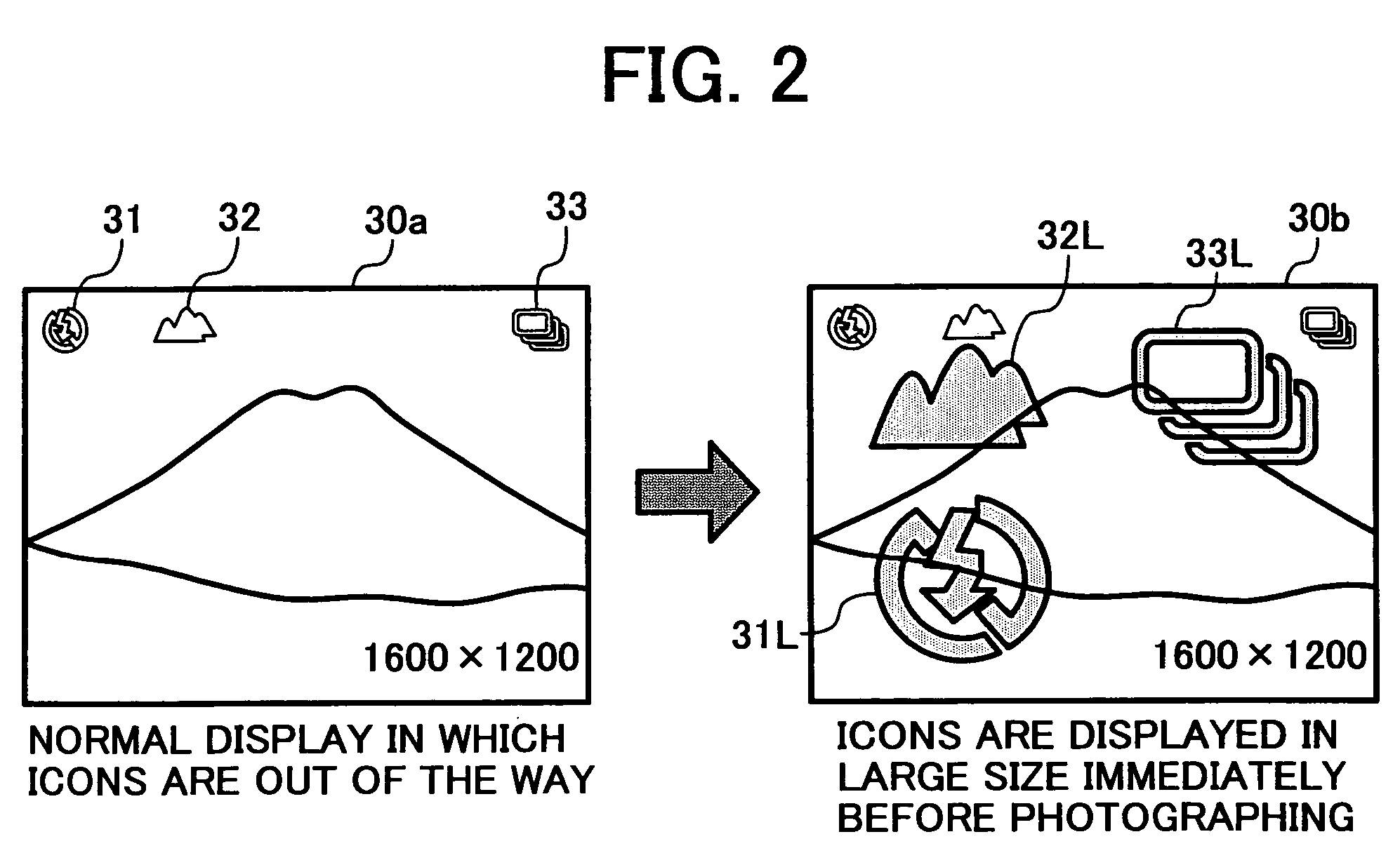
a technology of display unit and electronic equipment, applied in the field of electronic equipment with display unit, information processing method, and computer product, can solve the problems of affecting the display of base image data, poor visibility of characters that are set on the screen, and erroneous function setting,

Active Publication Date: 2005-09-29
RICOH KK
View PDF20 Cites 96 Cited by
  • Summary
  • Abstract
  • Description
  • Claims
  • Application Information

AI Technical Summary

Benefits of technology

[0012] An information-processing method according to another aspect of the present invention, which is for controlling an electronic apparatus with a display unit that can display icons indicating an apparatus state or an operating condition based on an on-screen display function, includes determining a change of the apparatus state or a change of a setting of the operating condition; assigning an icon indicating the apparatus state or the operating condition for which the change is detected at the determining; and displaying the icon assigned in a shape different from the icon before being assigned based on the on-screen display function.
[0012] An information-processing method according to another aspect of the present invention, which is for controlling an electronic apparatus with a display unit that can display icons indicating an apparatus state or an operating condition based on an on-screen display function, includes determining a change of the apparatus state or a change of a setting of the operating condition; assigning an icon indicating the apparatus state or the operating condition for which the change is detected at the determining; and displaying the icon assigned in a shape different from the icon before being assigned based on the on-screen display function.
[0018]FIG. 4 is a schematic for illustrating the LCD in which a display changes to a normal display after icons are enlarged based on the OSD function of the digital camera, according to the present embodiment;
[0019]FIG. 5 is a schematic for illustrating a change in the display of an enlarged icon on the screen;
[0020]FIG. 6 is a schematic for illustrating a user setting screen when a user uses an icon enlarged-display function, and a display screen following this setting, according to the present embodiment;
[0012] An information-processing method according to another aspect of the present invention, which is for controlling an electronic apparatus with a display unit that can display icons indicating an apparatus state or an operating condition based on an on-screen display function, includes determining a change of the apparatus state or a change of a setting of the operating condition; assigning an icon indicating the apparatus state or the operating condition for which the change is detected at the determining; and displaying the icon assigned in a shape different from the icon before being assigned based on the on-screen display function.
[0012] An information-processing method according to another aspect of the present invention, which is for controlling an electronic apparatus with a display unit that can display icons indicating an apparatus state or an operating condition based on an on-screen display function, includes determining a change of the apparatus state or a change of a setting of the operating condition; assigning an icon indicating the apparatus state or the operating condition for which the change is detected at the determining; and displaying the icon assigned in a shape different from the icon before being assigned based on the on-screen display function.
[0012] An information-processing method according to another aspect of the present invention, which is for controlling an electronic apparatus with a display unit that can display icons indicating an apparatus state or an operating condition based on an on-screen display function, includes determining a change of the apparatus state or a change of a setting of the operating condition; assigning an icon indicating the apparatus state or the operating condition for which the change is detected at the determining; and displaying the icon assigned in a shape different from the icon before being assigned based on the on-screen display function.
[0024]FIGS. 10A and 10B are schematics for illustrating a change of a screen from a change state set to a default setting; and
[0026] Exemplary embodiments of the present invention will be explained in detail with reference to the accompanying drawings. In the following embodiment, a digital camera is explained as the electronic apparatus. The present invention can be also applied to an electronic apparatus other than the digital camera having a compact display as a user interface in which a set operating mode and the like can be determined according to an icon display using an OSD function.
[0041] When a setting is changed based on an input operation from the operating unit 14, the on-screen-display controller 22 receives reference result information from the CPU 13 after the CPU 13 refers to a setting memory 23 held by the CPU 13, and the on-screen-display controller 22 selects an item of which setting is changed.
[0041] When a setting is changed based on an input operation from the operating unit 14, the on-screen-display controller 22 receives reference result information from the CPU 13 after the CPU 13 refers to a setting memory 23 held by the CPU 13, and the on-screen-display controller 22 selects an item of which setting is changed.
[0035] The operating unit 14 has operation buttons and the like to externally carry out a selection of a function, a photographing instruction, and various other settings. The on-screen-display controller 22 generates icon data, and outputs the generated icon data to the digital signal processing circuit 6 at timing of a dot clock in a predetermined cycle. The icon data includes character display data of a counter, a time, and a date, symbol data such as a photographing condition, and the like.
[0026] Exemplary embodiments of the present invention will be explained in detail with reference to the accompanying drawings. In the following embodiment, a digital camera is explained as the electronic apparatus. The present invention can be also applied to an electronic apparatus other than the digital camera having a compact display as a user interface in which a set operating mode and the like can be determined according to an icon display using an OSD function.
[0041] When a setting is changed based on an input operation from the operating unit 14, the on-screen-display controller 22 receives reference result information from the CPU 13 after the CPU 13 refers to a setting memory 23 held by the CPU 13, and the on-screen-display controller 22 selects an item of which setting is changed.
[0102] Furthermore, according to the present invention, a computer can execute the information-processing method according to the invention.

Problems solved by technology

When the icons are small, characters that are set on the screen have poor visibility because of garbled display.
The user cannot confirm the own setting, and may make an erroneous setting of functions.
When display sizes of the characters are increased to avoid the poor visibility, these characters may hinder the display of base image data.
Further, all the icons cannot be displayed because of the large size.

Method used


Image

  • Electronic apparatus with display unit, information-processing method, and computer product
  • Electronic apparatus with display unit, information-processing method, and computer product
  • Electronic apparatus with display unit, information-processing method, and computer product

Examples


Embodiment Construction

[0026] Exemplary embodiments of the present invention will be explained in detail with reference to the accompanying drawings. In the following embodiment, a digital camera is explained as the electronic apparatus. The present invention can be also applied to an electronic apparatus other than the digital camera having a compact display as a user interface in which a set operating mode and the like can be determined according to an icon display using an OSD function.

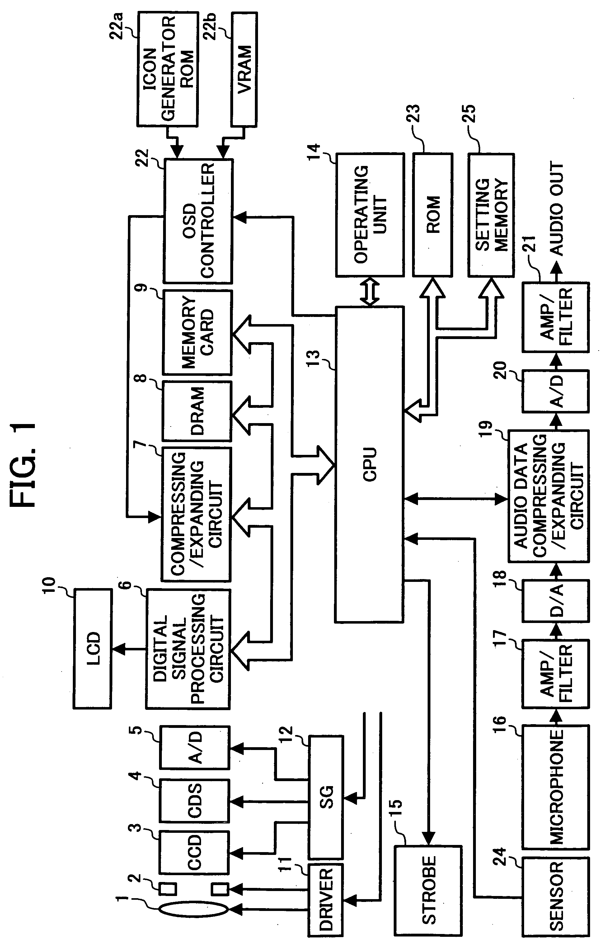
[0027]FIG. 1 is a block diagram of a basic configuration of the digital camera according to the present embodiment. The digital camera shown in FIG. 1 includes a lens 1, a mechanism 2 including an automatic focusing mechanism, a charge-coupled device (CCD) 3, a correlation double sampling (CDS) circuit 4, an analog / digital (A / D) converter 5, a digital signal processing circuit 6, a compressing / expanding circuit 7, a dynamic random access memory (DRAM) 8, a memory card 9, an LCD 10, a driver 11, a synchronous generator (...


PUM


Abstract

An electronic apparatus with a display unit that can display icons indicating an apparatus state or an operating condition based on an on-screen display function includes an apparatus-condition detecting unit that detects a change of the apparatus state or a change of a setting of the operating condition; an icon assigning unit that assigns an icon indicating the apparatus state or the operating condition for which the change is detected by the apparatus-condition detecting unit; and an on-screen-display controller that displays the icon assigned in a shape different from the icon before being assigned.

Description

CROSS-REFERENCE TO RELATED APPLICATIONS [0001] The present document incorporates by reference the entire contents of Japanese priority document, 2004-080795 filed in Japan on Mar. 19, 2004 and 2005-038267 filed in Japan on Feb. 15, 2005. BACKGROUND OF THE INVENTION [0002] 1) Field of the Invention [0003] The present invention relates to an electronic apparatus with a display unit, an information-processing method, and a computer product. [0004] 2) Description of the Related Art [0005] Recently, digital still cameras, portable telephones equipped with a digital camera, and the like are in widespread use as a media of image information. These apparatuses can provide various functions by handling the image information as electronic data. [0006] An on-screen display (OSD) function is one of those functions, so far used as a user interface. According to the OSD function, icons that indicate device states and operating conditions, characters, or the like are displayed in superimposition o...

Claims


Application Information

Patent Timeline
Patent Type & Authority Applications(United States)
IPC IPC(8): G03B17/18G06F3/0481G06F3/0484G06F3/0487G06F3/14G09G5/00H04N5/225H04N5/232H04N101/00
CPCH04N5/23293H04N23/634H04N23/632
Inventor SHINOHARA, MICHINARIMORIKAWA, HIROSHI
Owner RICOH KK
Why Eureka
Try Eureka