IOL injector

a technology of iol and iol insertion, which is applied in the field of ophthalmic surgical devices and methods, can solve the problems of iol expressing from the tip completely outside the eye, the inserter being decenter, and the surgeon so as to prevent the surgeon from losing control of the iol insertion process, and reduce the hoop strength of the tip

Active Publication Date: 2005-10-06
BAUSCH & LOMB INC
View PDF29 Cites 62 Cited by
  • Summary
  • Abstract
  • Description
  • Claims
  • Application Information

AI Technical Summary

Benefits of technology

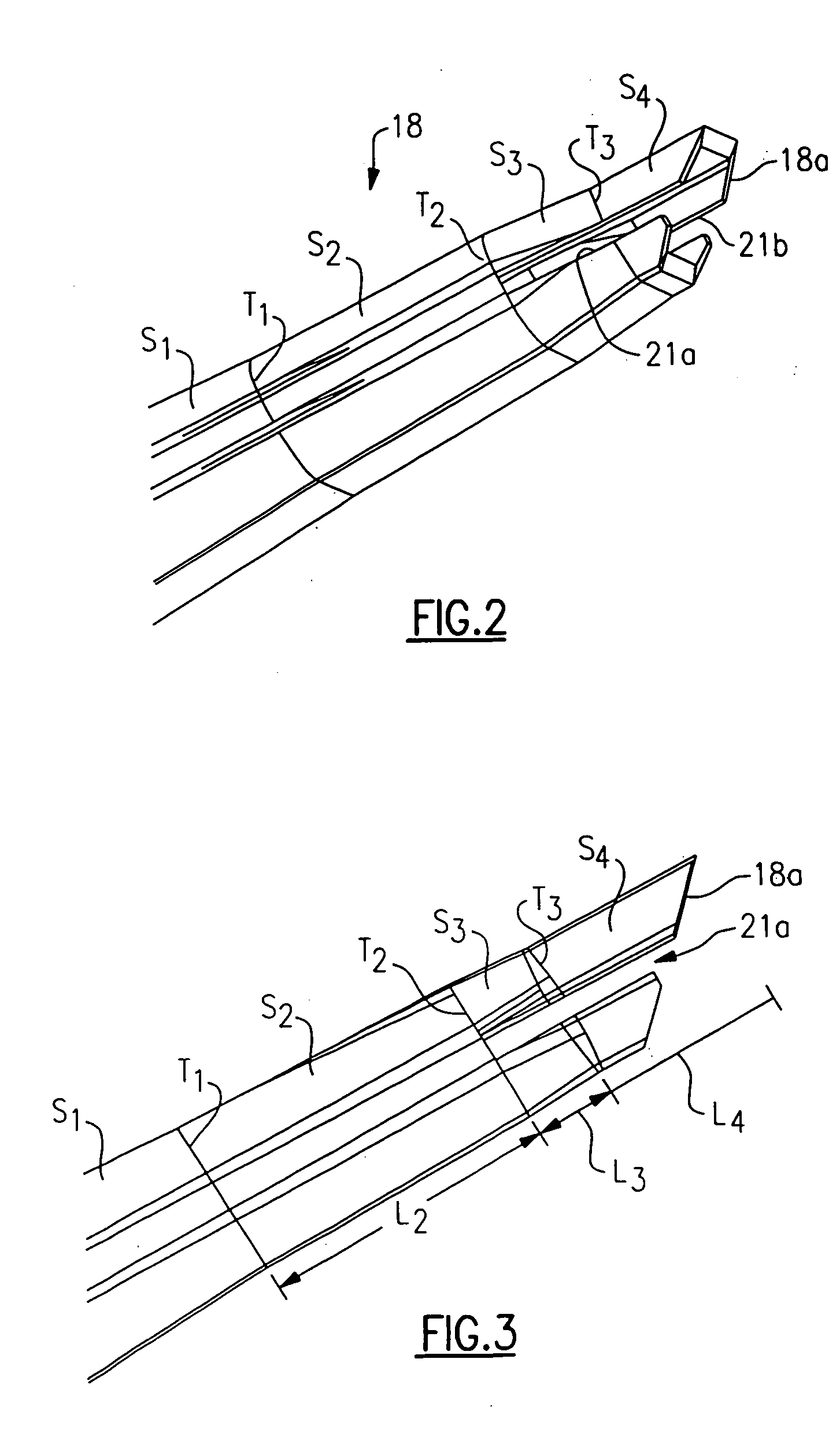
[0011] At least one but preferably two slots extend from the second transition point T2 to the tip open end face. The slots reduce the hoop (radial) strength of the tip along the third and fourth segments for reasons explained below. The slots may colinearly extend from respective grooves extending along the inside wall of the lumen through the tip wherein opposite sides of the IOL optic slide during passage of the IOL through the device and into the eye. Since the slots reduce the hoop strength of the tip along segments S3 and S4, those segments can spread outwardly under the force exerted by the compressed IOL as it travels through those segments. For surgeons who prefer to insert the tip only up to the third transition point T3, the fourth segment S4 will spread open within the eye as the IOL is passed therethrough. This spreading action of this portion of the tip effectively “anchors” the inserted portion (segment S4) of the tip in the eye until the IOL has completely exited the device. This anchoring effect is important in preventing the surgeon from losing control of the IOL insertion process, especially in those circumstances where the surgeon prefers to insert only up to the point of the third transition point T3 to maintain a very small diameter incision (i.e., in the range of about 2.0 to 2.5 mm). To explain, with only a small length of the tip inserted through the incision (i.e., up to point T3), and without such anchoring of the tip within the eye, the force of the IOL exiting the tip may cause an inserter to decenter and / or kick back from the incision, possibly resulting in incorrect placement within the eye or the IOL expressing from the tip completely outside of the eye. The anchoring effect of the inventive tip thus ensures the tip will remain centered in the incision and in the eye until the IOL is completely expressed from the tip. Once the IOL is fully expressed from the tip into the eye, the resiliency of the tip causes the tip to return to its normal diameter allowing easy withdrawl from the eye with no stretching of the incision.

Problems solved by technology

To explain, with only a small length of the tip inserted through the incision (i.e., up to point T3), and without such anchoring of the tip within the eye, the force of the IOL exiting the tip may cause an inserter to decenter and / or kick back from the incision, possibly resulting in incorrect placement within the eye or the IOL expressing from the tip completely outside of the eye.

Method used


Image

  • IOL injector
  • IOL injector
  • IOL injector

Examples


Embodiment Construction

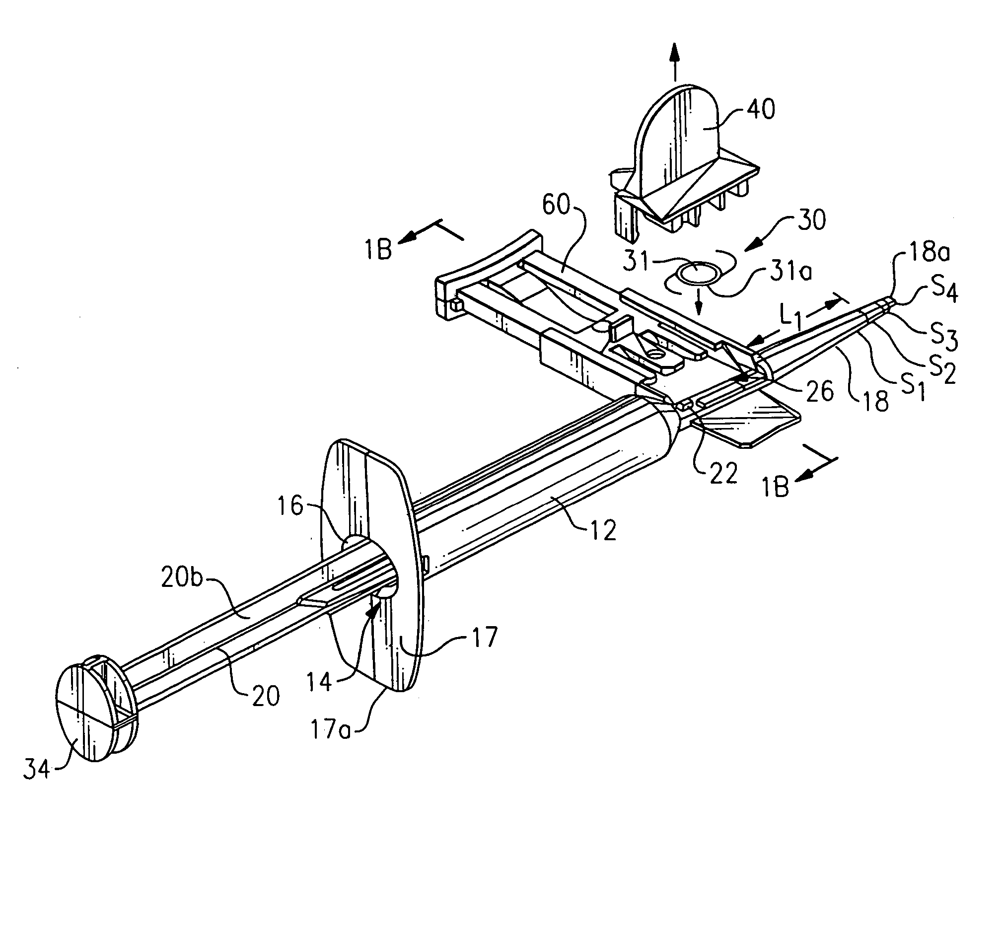
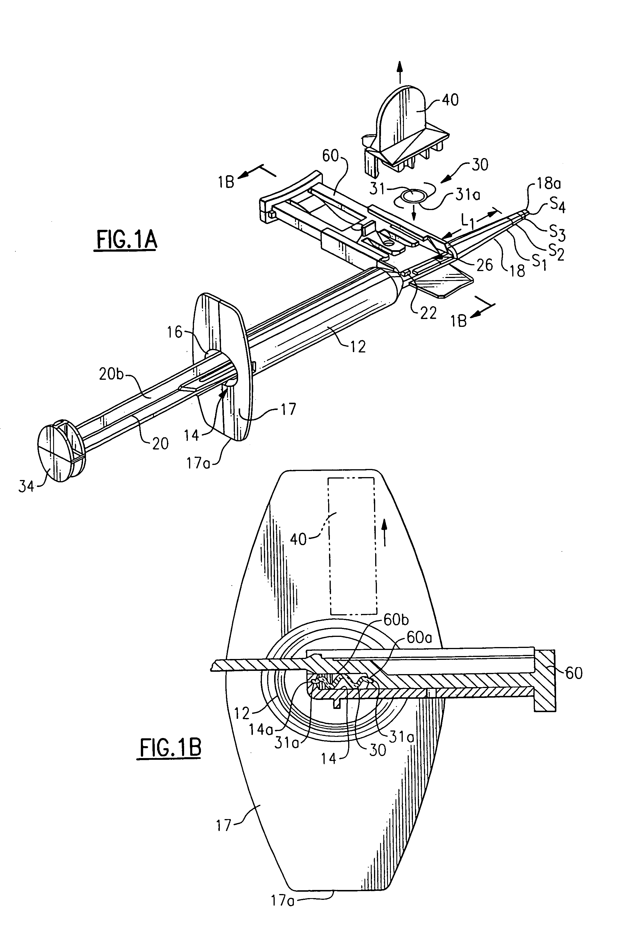
[0019] Referring to FIG. 1A, a representative IOL injector device is indicated generally by the reference numeral 10. The injector device 10 includes an injector body 12 having a longitudinal lumen 14 extending from the proximal end 16 to distal open end 18a thereof. The lumen may assume any desired cross-sectional shape although circular or oval shapes are preferred. Proximal end 16 may include a finger hold flange 17 preferably configured with a straight edge 17a as shown for resting device 10 on a flat surface. A plunger 20, having a distal plunger tip 22 and proximal thumb press 24, telescopes within lumen 14 for engaging and pushing the IOL 30 through lumen 14 and out of distal tip 18a. It is understood that the overall configuration of the injector body 12 may vary from that shown and described herein. It is furthermore understood that the components of the injector device 10 may be made of any suitable material (e.g., polypropylene) and may be wholly or partly opaque, transpa...


PUM


Abstract

A device for injecting an intraocular lens (IOL) into an eye, the device having an injector body including a lumen and an open tip wherethrough the IOL is expressed from the device. An IOL loading bay is located in the passageway wherein the IOL is positioned and compressed. The injector tip is dimensioned to allow the surgeon to choose an insertion depth between first, second and third transition points defined on the tip, the first and second transition points having a larger diameter than the third transition point which is located closer to the open tend of the tip. If the surgeon wishes to insert through a very small incision size (e.g., about 2.4 mm), the surgeon will insert the tip only up to the third transition point. The injector is stable during delivery of the IOL therethrough due to a spreading of the tip within the eye which effectively anchors the tip during IOL delivery.

Description

BACKGROUND OF THE INVENTION [0001] The present invention relates to ophthalmic surgical devices and methods. More particularly, the present invention relates to a device and method for inserting an intraocular lens (IOL) into an eye. [0002] IOLs are artificial lenses used to replace the natural crystalline lens of the eye when the natural lens has cataracts or is otherwise diseased. IOLs are also sometimes implanted into an eye to correct refractive errors of the eye in which case the natural lens may remain in the eye together with the implanted IOL. The IOL may be placed in either the posterior chamber or anterior chamber of the eye. IOLs come in a variety of configurations and materials. Some common IOL styles include the so-called open-looped haptics which include the three-piece type having an optic and two haptics attached to and extending from the optic; the one-piece type wherein the optic and haptics are integrally formed (e.g., by machining the optic and haptics together f...

Claims


Application Information

Patent Timeline
Patent Type & Authority Applications(United States)
IPC IPC(8): A61F2/16
CPCA61F2/1678
Inventor VAQUERO, EDWARD
Owner BAUSCH & LOMB INC
Why Eureka
Try Eureka