Correction of loss and dispersion in cable fault measurements

a loss and dispersion correction and fault measurement technology, applied in the direction of resistance/reactance/impedence, line-transmission details, instruments, etc., can solve the problems of dispersion distortion, inaccuracy of methods, attenuation distortion, etc., and achieve the effect of removing all loss and dispersion distortion components

Active Publication Date: 2005-10-13
JOHN FLUKE MFG CO INC
View PDF7 Cites 7 Cited by
  • Summary
  • Abstract
  • Description
  • Claims
  • Application Information

AI Technical Summary

Benefits of technology

[0010] The loss and dispersion correction method of the present invention is useful in providing clear and accurate reflected responses in both pulse-based cable test instruments and frequency-based cable test instruments.
[0011] A cable is measured in the frequency domain to obtain a reflected response. In the case of a pulse-based instrument, a Fourier transform is used to decompose a sent pulse into its sinusoidal components. A superposition of fractional sinusoidal components of the reflected response having attenuated amplitude and delayed phase values at points defining the junctures of adjacent equal predetermined lengths along the cable are collected and normalized. Then the fractional sinusoidal components of the reflected response are extracted from normalized superposition by mathematically calculating the real value at each point, thereby removing all loss and dispersion distortion components.

Problems solved by technology

Attenuation distortion is due to losses in a cable.
Because the weighting function corrects only for attenuation and not for dispersion, this method is prone to inaccuracies.
Further, this method also corrects only for attenuation, and not for dispersion.
The second type of distortion, dispersion distortion, results from the fact that the different frequency components of the stimulus signals and reflections propagate through the cable at different speeds.
The effect of these distortions is reduce the instrument operator's ability to recognize “events” or faults in the cable.

Method used


Image

  • Correction of loss and dispersion in cable fault measurements
  • Correction of loss and dispersion in cable fault measurements
  • Correction of loss and dispersion in cable fault measurements

Examples


Embodiment Construction

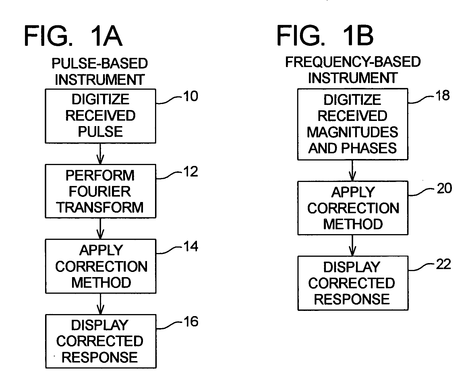
[0017]FIGS. 1A and 1B show a flow chart comparison of pulse-based cable test instruments and frequency-based instruments for carrying out the correction method of the present invention. Considering first FIG. 1A, a pulse-based test instrument sends a short-duration pulse into a cable under test and receives a reflected response in the time domain. In block 10, the reflected response received from the cable is “digitized,” that is, the response is sampled at a predetermined clock rate and converted to digital representations that can then be processed. In block 12, a Fourier transform transforms the digitized response from the time domain to the frequency domain. In block 14, the correction method of the present invention is applied. In block 16, the corrected response is displayed.

[0018] In FIG. 1B, a frequency-based test instrument synthesizes a virtual stimulus pulse by sending a series of sinusoidal frequencies, or “tones,” into a cable under test. Reflected responses are receiv...


PUM


Abstract

A method of correcting distortions resulting from loss and dispersion in cable fault measurements. A cable is measured in the frequency domain to obtain a reflected response. Fractional sinusoidal components of the reflected response having attenuated amplitude and delayed phase values at points defining the junctures of adjacent equal predetermined lengths are collected and normalized. Then the fractional sinusoidal components of the reflected response are extracted from normalized sum by mathematically calculating the real value at each point, thereby removing all loss and dispersion distortion components.

Description

BACKGROUND OF THE INVENTION [0001] This invention relates generally to cable fault measurements, and in particular to correction of loss and dispersion in cable fault measurements. [0002] In testing and troubleshooting electrical cables, which may be either single-wire cables or twisted-wire pairs, a typical test involves using test instruments that transmit stimulus signals into one end of a cable and receive and measure any reflections that return. Both time-domain reflectometry (TDR) and time-domain crosstalk (TDX) measurements are subject to two major types of distortion. One is attenuation distortion and the other is dispersion distortion. [0003] Attenuation distortion is due to losses in a cable. That is, energy is lost as a stimulus signal propagates down a cable under test and then is reflected back to the test instrument, with the result being that received signals become smaller in magnitude to the point they may no longer be discernible. [0004] One prior art method of cor...

Claims


Application Information

Patent Timeline
Patent Type & Authority Applications(United States)
IPC IPC(8): G01R27/28H04B3/46G01R31/11G01R31/02G01R31/08G01R35/00
CPCG01R31/11G01R27/28H04B3/46G01R31/08
Inventor OAKLEY, PETER Q.
Owner JOHN FLUKE MFG CO INC
Why Eureka
Try Eureka