Crown molding with lighting effects

a crown molding and lighting effect technology, applied in the field of indirect lighting systems, can solve the problems of virtually inconspicuous lighting system, prior art fails to teach a decorative crown molding system using long, and prior art fails to teach such a crown molding produ

Inactive Publication Date: 2005-10-13
HAHN RICHARD
View PDF17 Cites 14 Cited by
  • Summary
  • Abstract
  • Description
  • Claims
  • Application Information

AI Technical Summary

Benefits of technology

[0025] A still further objective is to provide a means for projecting a lighting effect from the crown molding.

Problems solved by technology

Because the architectural moldings are constructed to appear like conventional trims or moldings, the lighting system is virtually inconspicuous when attached to a house, building or other architectural structure, such as a fence or garage.
However, the prior art fails to teach a decorative crown molding system using long lighting elements mounted in grooves formed in spaced apart integrally molded-in webs.
The prior art also fails to teach such a crown molding product with arrays of slots of a size, placement, and density as to provide significant light effects directed downwardly and to provide sufficient cooling of air movement upward and around the lighting fixtures.

Method used


Image

  • Crown molding with lighting effects
  • Crown molding with lighting effects
  • Crown molding with lighting effects

Examples


Embodiment Construction

[0032] The above described drawing figures illustrate the described apparatus and its method of use in at least one of its preferred, best mode embodiment, which is further defined in detail in the following description. Those having ordinary skill in the art may be able to make alterations and modifications what is described herein without departing from its spirit and scope. Therefore, it must be understood that what is illustrated is set forth only for the purposes of example and that it should not be taken as a limitation in the scope of the present apparatus and method of use.

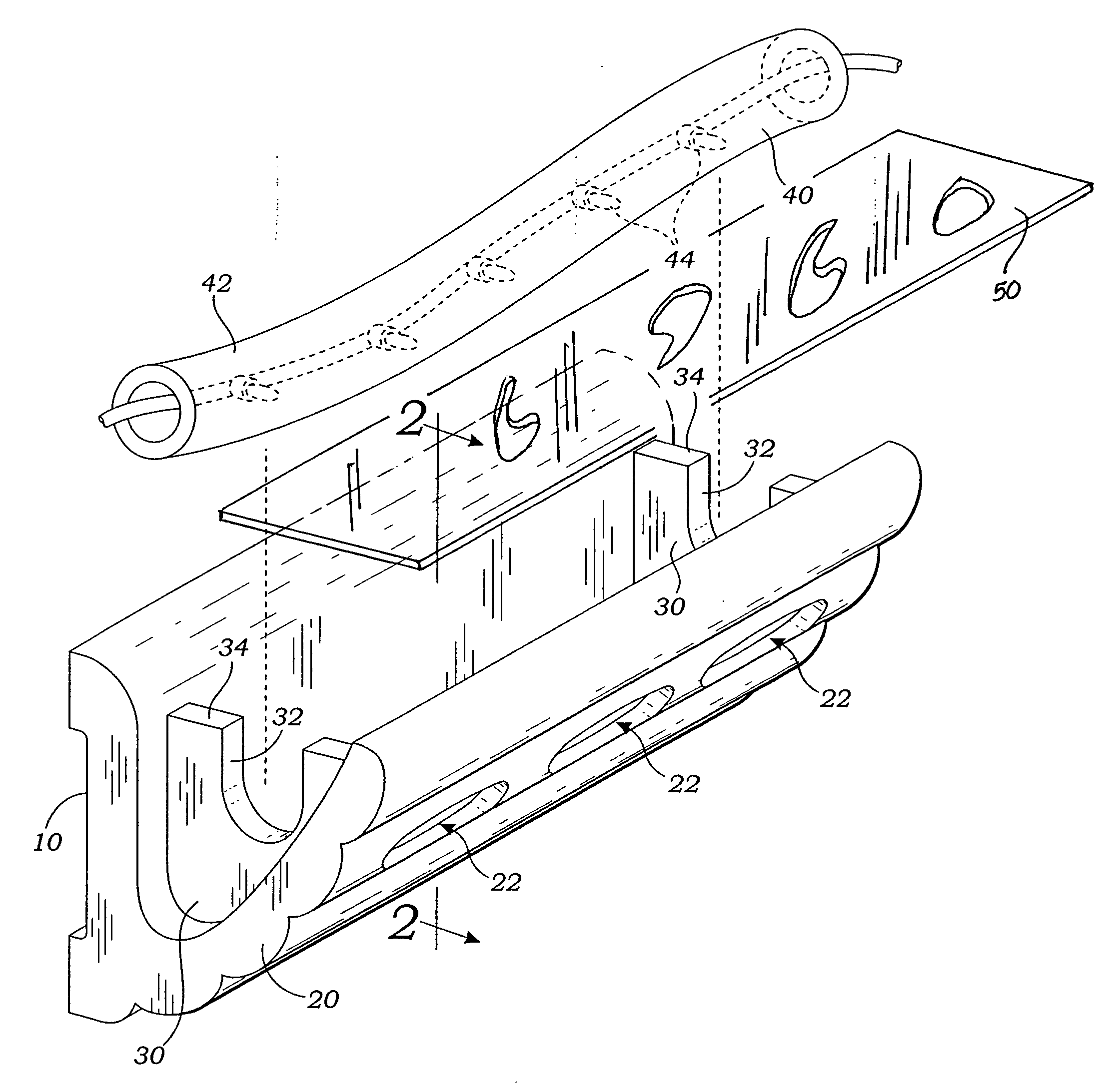
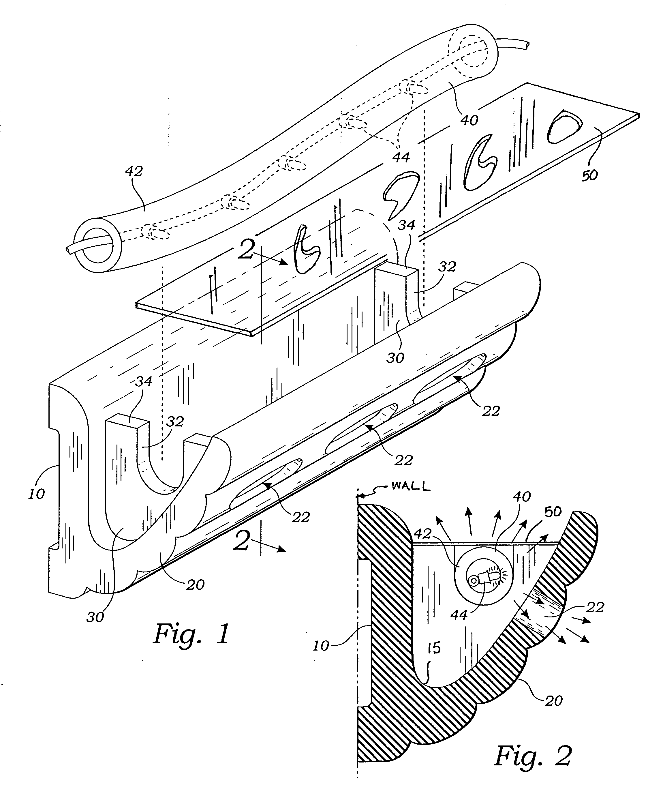
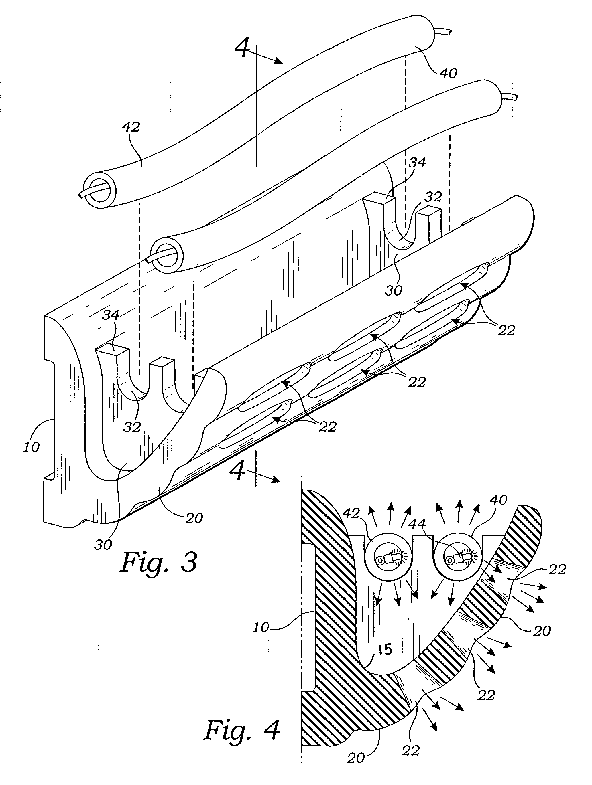
[0033] The present crown molding apparatus provides a vertically oriented mounting leg 10 joined with an outwardly angled decorative leg 20 in a modified “V” configuration, as shown in FIGS. 2 and 4. A plurality of spaced apart webs 30 are preferably oriented normal to the mounting and decorative legs and extensive between them. Preferably, the webs 30 are molded integrally with the legs 10 and 20, althou...


PUM


Abstract

A crown molding has a vertically oriented mounting leg joined with an outwardly angled decorative leg in a modified “V” configuration. A plurality of spaced apart webs are each extensive between the mounting leg and the decorative leg. Each of the webs provides at least one concave groove on an upwardly directed top edge, thereby forming a plurality of such grooves in longitudinally spaced apart positions. A flexible lighting tube is engaged within the grooves and extensive longitudinally. Apertures are placed in the decorative leg to allow light from the lighting tube to filter downwardly.

Description

RELATED APPLICATIONS [0001] This application is a Continuation In Part Application of a prior filed application having Ser. No. 10 / 359,381 and filing date of Feb. 5, 2003 and entitled: Wall Molding Mounting Structure And Method and is related to Ser. No. 10 / 810,936 filed on Mar. 26, 2004.BACKGROUND [0002] 1. Field of the Present Disclosure [0003] This disclosure relates generally to indirect lighting systems for rooms and also to crown molding structures for improving the appearance of interior spaces, and more particularly to a crown molding system with indirect lighting features. [0004] 2. Description of Related Art [0005] The following art defines the present state of this field and each U.S. disclosure is hereby incorporated herein by reference: [0006] Richter, U.S. Pat. No. 1,249,500 describes the combination of interior illumination with the walls of a room, of a removably light confining trough involving a supporting body structure designed to contact with and be securely fas...

Claims


Application Information

Patent Timeline
Patent Type & Authority Applications(United States)
IPC IPC(8): E04B2/00F21S4/00F21S8/00F21V7/00F21V9/08F21V11/12F21V33/00
CPCF21S4/005F21V7/0016F21V33/006F21V11/12F21V9/08F21S4/22
Inventor HAHN, RICHARD
Owner HAHN RICHARD
Why Eureka
Try Eureka