Upload shank swivel head bone screw spinal implant

a bone screw and head technology, applied in the field of polyaxial bone screws, can solve the problems of difficult or impossible to do, undesirable for implant pieces to be free to move around within the body, etc., and achieve the effects of preventing further rotation, reducing the height of the screw head, and improving the mechanical

Inactive Publication Date: 2005-10-13
JACKSON
View PDF30 Cites 123 Cited by
  • Summary
  • Abstract
  • Description
  • Claims
  • Application Information

AI Technical Summary

Problems solved by technology

This is sometimes very difficult or impossible to do so polyaxial bone screws are commonly used.
It is very undesirable for pieces of the implant to be free to move around within the body after surgery is completed and it also assures that the implant retains an ability to correct the structural problem for which it was implanted.

Method used


Image

  • Upload shank swivel head bone screw spinal implant
  • Upload shank swivel head bone screw spinal implant
  • Upload shank swivel head bone screw spinal implant

Examples


second embodiment

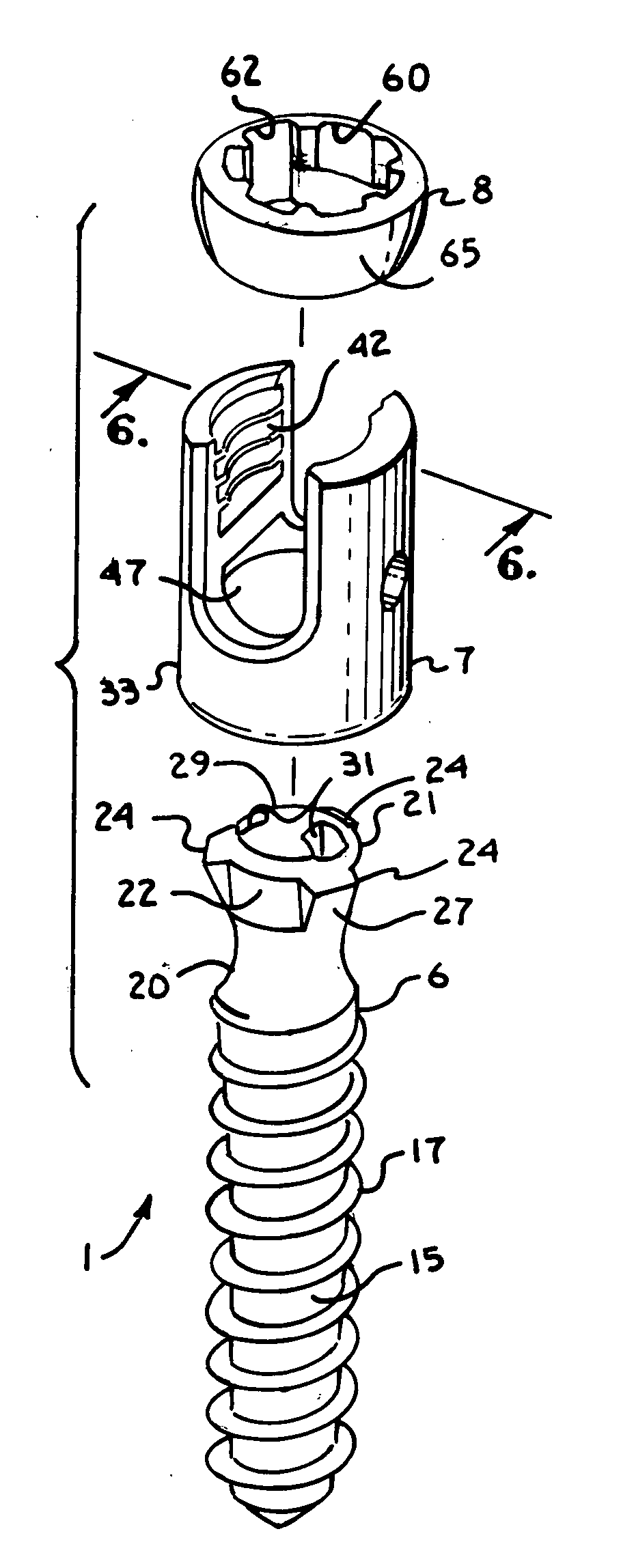
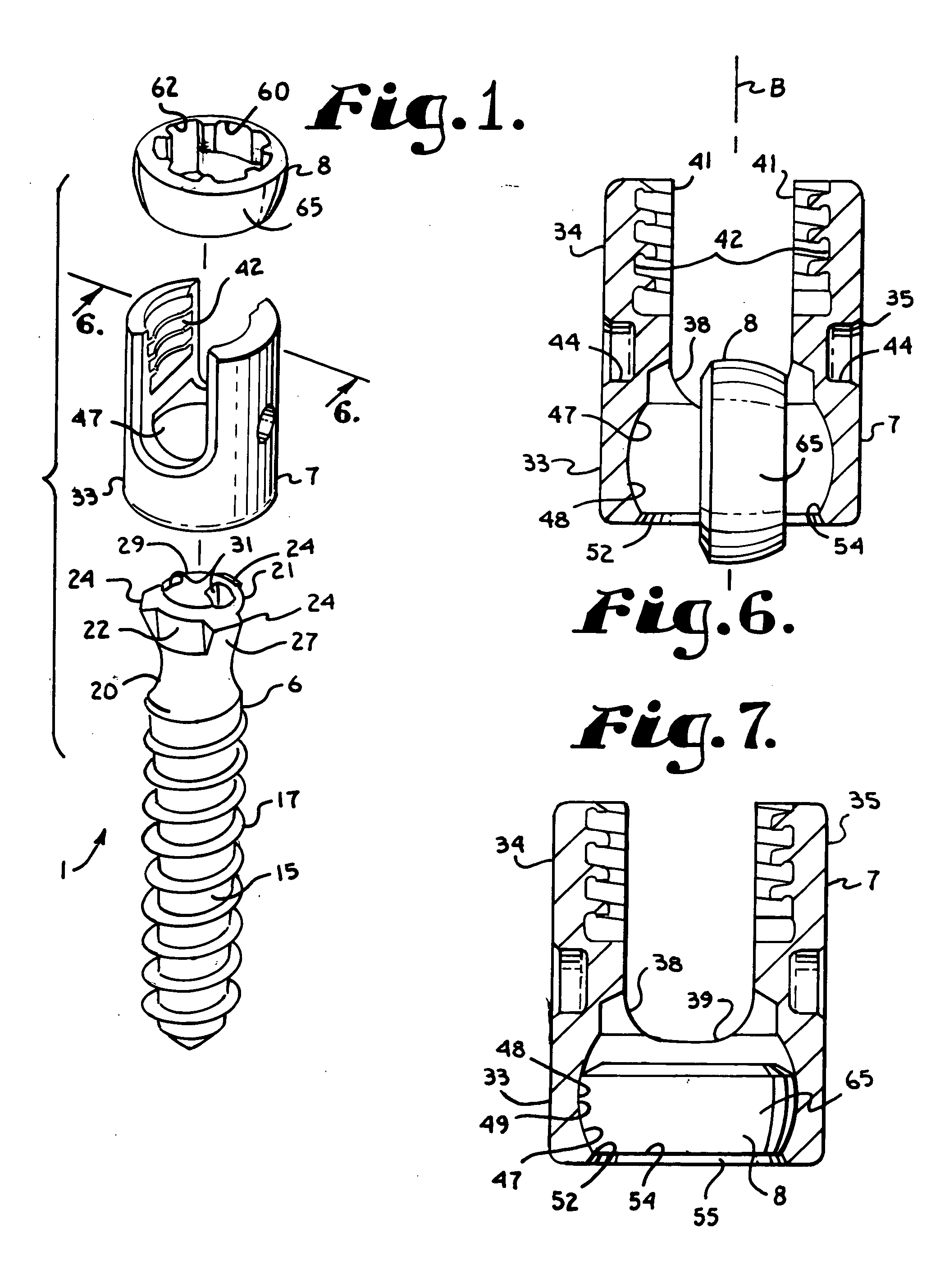
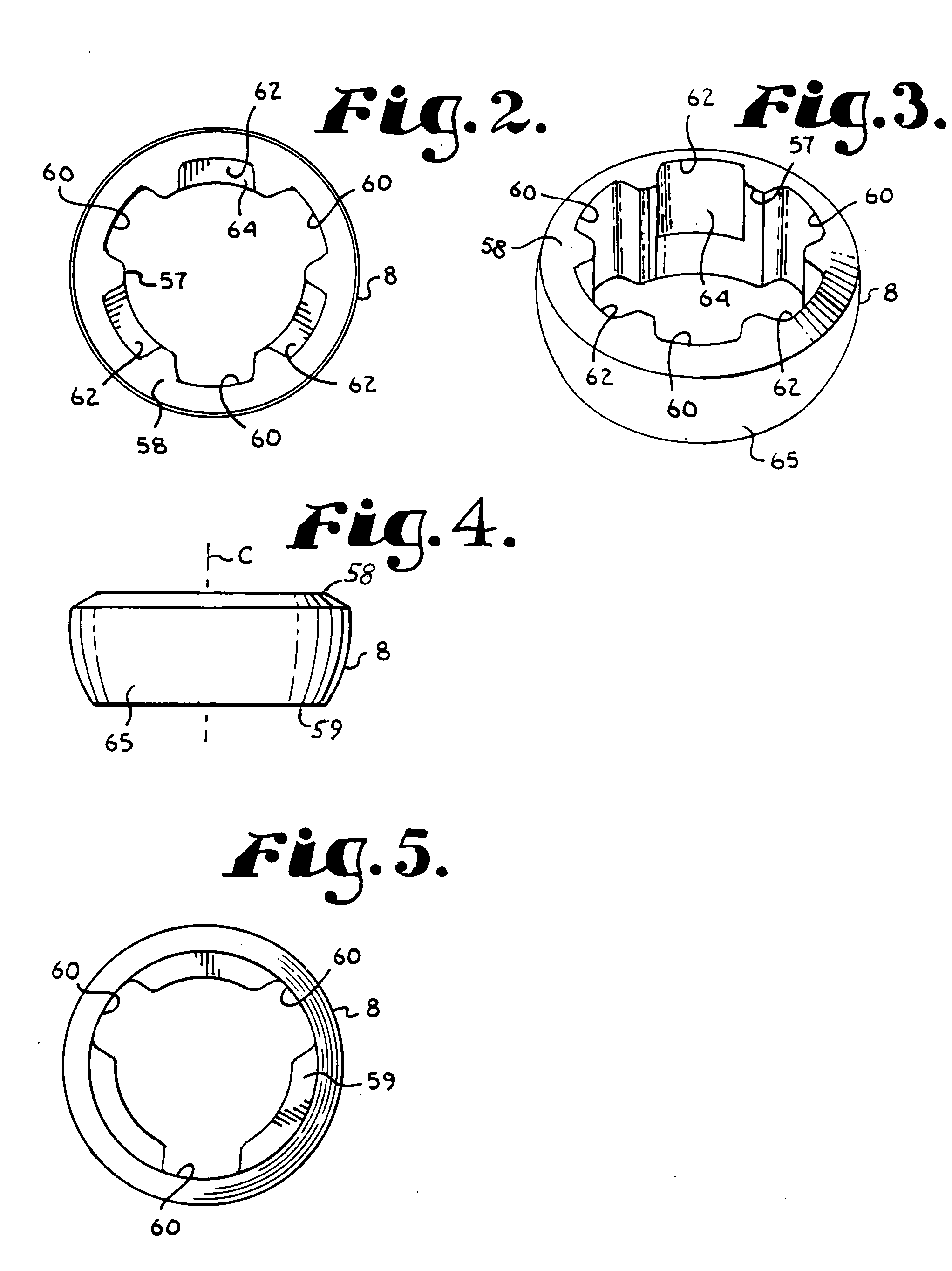
[0060] Illustrated in FIG. 19 is a retainer ring 88 in accordance with the present invention. The retainer ring 88 is quite similar to the retainer ring 8 of the previous embodiment except that it is noncontinuous and has a radially extending space or gap 90 from top to bottom along one side thereof. The gap 90 allows for expansion without requiring stretching of the material of construction of the ring 88, as is the case with the previous embodiment. The ring 88 includes a central bore 92, spline channels 93 and spline receivers 94 which are all similar to the similar structures described for the previous embodiment. The retainer ring 88 also has a partial hemispherical shaped surface 95 on the outer side thereof.

[0061] Illustrated in FIGS. 20 and 21 are elements of a third embodiment of the present invention including a shank 106 and a capture ring 107 which are used otherwise in the same manner as has been described in the first embodiment and, in particular, with a head such as ...

first embodiment

[0062] The capture ring 107, shown in FIG. 21, is otherwise similar to the retainer ring 8 except that it includes a set of four channels 126 and four recesses 127 that are sized shaped and positioned so as with respect to the channels 126 to allow the splines 120 to slidingly pass upwardly through and with respect to the recesses 127 to capture and receive the splines 120, as they move axially downwardly. The ring 107 has a partial hemispherical outer surface 129 that mates with the corresponding surface in the head 7 in the manner described for the


PUM

PropertyMeasurementUnit
torqueaaaaaaaaaa
heightaaaaaaaaaa
widthaaaaaaaaaa

Abstract

A polyaxial bone screw having a bone implantable shank, a head and a retaining ring. The retaining ring includes an outer partial hemispherical surface and an inner bore with radially extending channels and partial capture recesses. The shank includes a bone implantable body with an external helical wound thread and an upwardly extending capture structure. The capture structure includes at least one spline which extends radially outward and has a wedged surface that faces radially outward therefrom. The capture structure operably passes through a central bore of the retaining ring while the spline passes through a suitably shaped channel so that the spline becomes positioned above the head at which time the shank is rotated appropriately and the shank is drawn back downwardly so that the spline engages and seats in the capture recess. The head includes an internal cavity having a spherical shaped surface that mates with the ring surface and has a lower restrictive neck that prevents passage of the ring once the ring is seated in the cavity.

Description

BACKGROUND OF THE INVENTION [0001] The present invention is directed to a polyaxial bone screw for use in spinal surgery and the like and especially to such a screw adapted to receive a rod member and secure the rod member to a vertebra or the like. [0002] Many spinal surgery procedures require securing various implants to bone and especially to vertebrae along the spine. For example, elongate rods are often required that extend along the spine to provide support to vertebrae that have been damaged or weakened due to injury, disease or the like. Such rods must be supported by certain vertebra and support other vertebra. The most common mechanism for providing such structure is to implant bone screws into certain bones which then in turn support the rod or are supported by the rod. Bone screws of this type may have a fixed head relative to a shank thereof. In the fixed bone screws, the head cannot be moved relative to the shank and the rod must be favorably positioned in order for it...

Claims


Application Information

Patent Timeline
Patent Type & Authority Applications(United States)
IPC IPC(8): A61B17/58A61B17/70
CPCA61B17/7032Y10T29/49826A61B17/7037
Inventor JACKSON, ROGER P.
Owner JACKSON
Why Eureka
Try Eureka