
System, method and computer program product for forming a reconfigurable cavity and an expandable shoe last and for constructing a shoe

a technology of reconfigurable cavity and expandable shoe body, applied in the field of apparatus, systems and methods for producing shoe body, can solve the problems of high labor intensity, disadvantageous use of mechanical machinery for lasting operation, frequent complicated maintenance,

Inactive Publication Date: 2002-02-28
SAJEDI MOHAMMAD H
View PDF0 Cites 82 Cited by
  • Summary
  • Abstract
  • Description
  • Claims
  • Application Information

AI Technical Summary

Problems solved by technology

To date, last mass-production from plastic last block still generally follows the above mentioned twenty-one step sequence of operations which is conventionally of very high cost and is very labor intensive.
Another lengthy part of the mass-production process cycle that also requires skilled labor is sample shoes.
Conventionally, employing mechanical machinery for the lasting operation is disadvantageous because it requires elaborate and lengthy setup time and is very expensive.
Mechanical machinery also requires high capital investment, frequent complicated maintenance, and much energy.
Again, elaborate and costly equipment, setup and skilled labor are involved in producing a pair of custom-made lasts.

Method used


Image

  • System, method and computer program product for forming a reconfigurable cavity and an expandable shoe last and for constructing a shoe
  • System, method and computer program product for forming a reconfigurable cavity and an expandable shoe last and for constructing a shoe
  • System, method and computer program product for forming a reconfigurable cavity and an expandable shoe last and for constructing a shoe

Examples


Embodiment Construction

[0091] A preferred embodiment of the invention is discussed in detail below. While specific exemplary implementation embodiments are discussed, it should be understood that this is done for illustration purposes only. A person skilled in the relevant art / profession recognizes that other components and configurations may be used without parting from the spirit and scope of the invention.

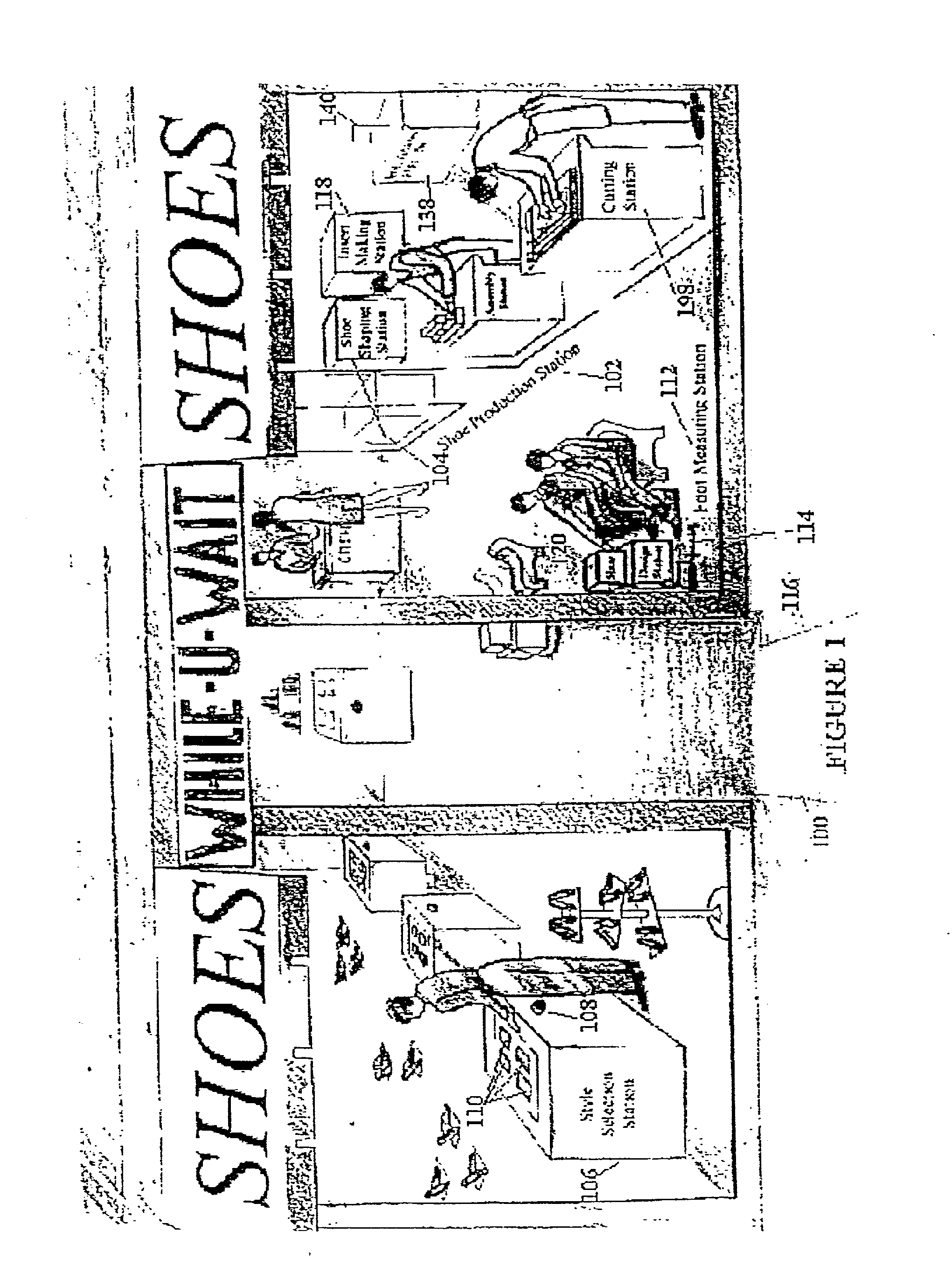
[0092] An example embodiment of a blow molding apparatus 104 as an element of a custom-made shoe making system 102 in accordance with the present invention is illustrated in an exemplary shoe store layout 100 of FIG. 1. The store layout 100 can include a style selection area 106, which can allow a customer to choose a desired shoe style from a shoe catalog. To help the customer to choose a virtual pair of shoes, a camera 108 can capture lower body image (waist down) from different directions and can display each image on a separate display screen 110. After choosing the most suitable shoe style, the c...


PUM

PropertyMeasurementUnit
Lengthaaaaaaaaaa
Shapeaaaaaaaaaa
Widthaaaaaaaaaa

Abstract

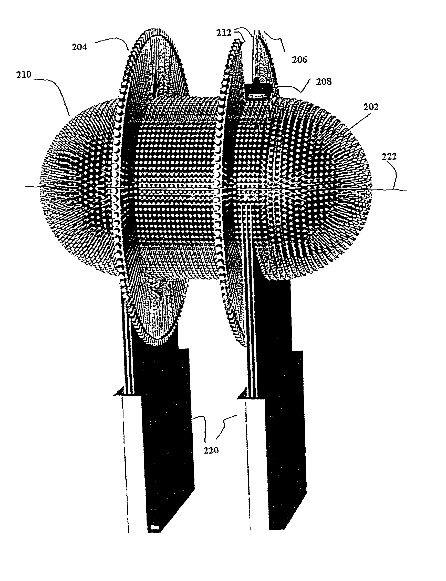
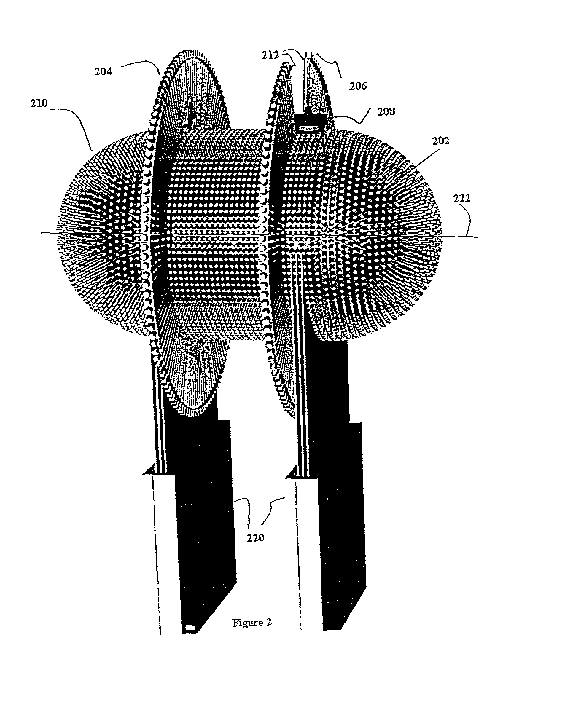
The present invention is an exemplary embodiment of the present invention is directed to a system, method and computer program product for creating a three-dimensionally reconfigurable cavity. The system can include a container that is configurable to create a three dimensional cavity. The system can be operative to form a footwear last in the cavity. The last can be formed from a plastic-like material. The system can include a blow molding apparatus having at least one directional deflector. The container can be capsule, hemispherical, cylindrical, or spherical-shaped. The system can include a container having holes to receive rods. The system can include an array of rods. The rods can be movable through the container. The system can further include rods that are threaded; gear-driven; coupled to a belt; coupled to a partial belt; or belt-driven. The cavity can be formed by an inner end of the rods. If more than one rod occupies a single point of the cavity, then only one rod participates in forming the cavity and other rods will not participate. Participating rods can be selected according to an optimizing module. The software module can determine an intersection of a rod with a digitized cluster of points representing a 3 dimensional surface. A method of forming a footwear last from a collapsible and expandable last is described.

Description

[0001] 1. Field of the Invention[0002] This invention relates generally to an apparatus, systems and methods for producing a shoe last and a related method of shoe construction.[0003] 2. Related Art[0004] As is apparent to those skilled in the art and the profession, "lasts" are fundamental to mass-production or custom-made shoe manufacturing, since lasts dictate the exact shape, size and fit of the shoes made on the lasts. Last design can depend on fashion trends as well as on anatomy of the foot.[0005] Conventionally, in a shoe mass-production process cycle, a last stylist must be able to forecast fashionable shoe styles about one year before the shoes are to be sold in shops. The stylist can create a model last using a 3D computerized last design software package and a Computer Numerical Control (CNC) cutting machine or a traditional method of carving the model last from a block of wood. The model is then prepared for turning a pair of sample size lasts. The sample lasts are used...

Claims


Application Information

Patent Timeline
IPC IPC(8): A43D1/04A43D3/02A43D3/04B29C49/00B29D35/00
CPCA43D1/04A43D3/027A43D3/04B29C49/00B29D35/0018B29L2031/50
Inventor SAJEDI, MOHAMMAD HASSANHEMAMI, AHMAD
Owner SAJEDI MOHAMMAD H
Learn More