[0029] The present invention may be understood more readily by reference to the following detailed description of the invention taken in connection with the accompanying drawing figures, which form a part of this disclosure. It is to be understood that this invention is not limited to the specific devices, methods, conditions or parameters described and/or shown herein, and that the terminology used herein is for the purpose of describing particular embodiments by way of example only and is not intended to be limiting of the claimed invention. Also, as used in the specification including the appended claims, the singular forms “a,”“an,” and “the” include the plural, and reference to a particular numerical value includes at least that particular value, unless the context clearly dictates otherwise. Ranges may be expressed herein as from “about” or “approximately” one particular value and/or to “about” or “approximately” another particular value. When such a range is expressed, another embodiment includes from the one particular value and/or to the other particular value. Similarly, when values are expressed as approximations, by use of the antecedent “about,” it will be understood that the particular value forms another embodiment.
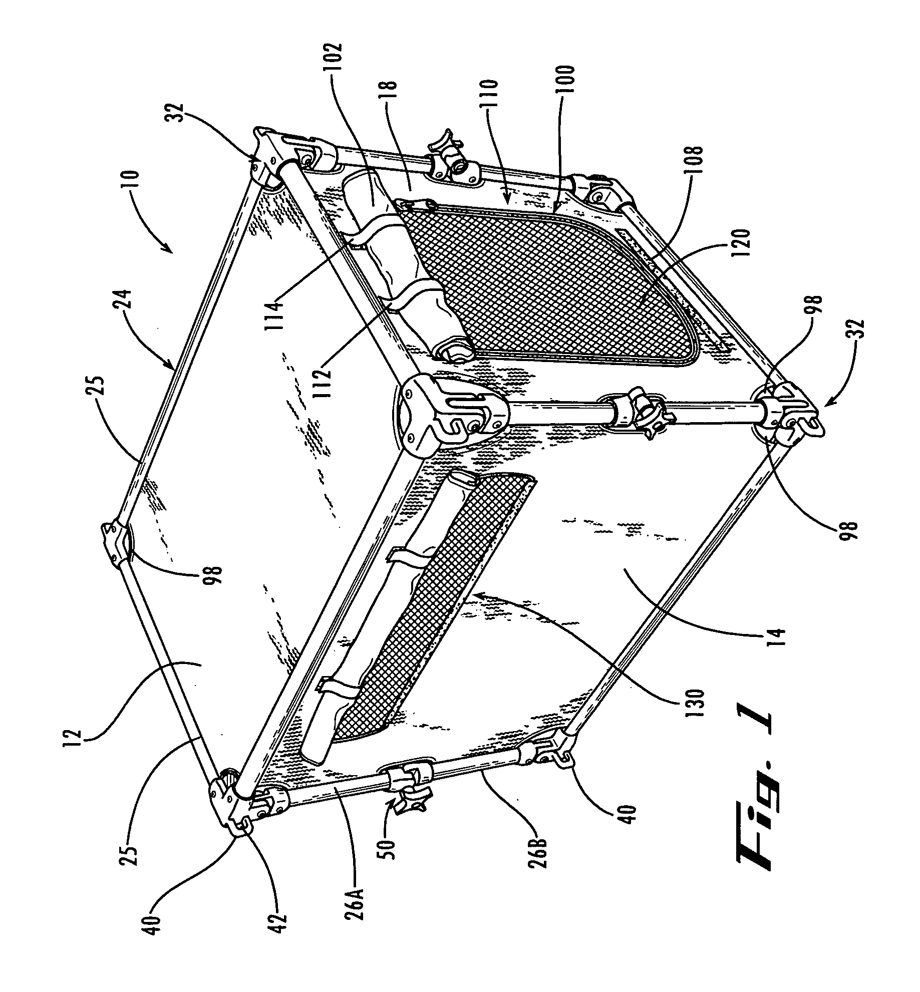
[0030] With reference now to the drawing figures, a pet housing 10 is shown by way of example embodiments of the present invention. In its assembled and upright configuration, the pet housing 10 preferably comprises a plurality of generally rectangular panels, preferably including a top panel 12; first and second side panels 14, 16; a front panel 18; a back panel 20; and a bottom panel 22, as shown in FIGS. 1-3, secured to a rigid, load-bearing frame 24. When the housing is in this assembled or set-up configuration as shown in FIG. 1, the side panels 14, 16 and the end panels 18, 20 are upright and generally perpendicular to the generally horizontal bottom panel 22; the side panels 14, 16 are generally parallel to one another and generally perpendicular to the end panels 18, 20; and the top panel 12 is generally perpendicular to the side panels 14, 16 and the end panels 18, 20; thereby forming a generally rectangular box-like structure with an interior chamber for housing a pet.
[0031] The top, end, and side panels are preferably constructed of a durable flexible fabric such as ballistic nylon or canvas. The bottom panel 22 preferably is constructed of a more durable material, such as a metal or hard plastic. Preferably, the bottom panel 22 resembles a tray and is permanently secured to the frame 24. In alternate embodiments, the floor panel can be removably secured to the frame 24. The bottom panel 22 can also include a plurality of cross-slats 23 or supports for added stability. In an open configuration, the panels preferably have a tight fabric finish.
[0032] The frame 24 preferably comprises a plurality of tubular end and side rails 25 and posts 26, each preferably comprising anodized extruded aluminum, plastic or other structural material. A plurality of pairs of generally upright corner posts 26 engage ends of the side panels and the end panels. A plurality of lateral rails 25 connects the end and side panels to the upper and lower panels. Preferably, the rails 25 and posts 26 have cross sections as depicted in FIG. 4, with two channels or slits 28, 30 extending along their length, one slit for receiving and securing the edge of a first panel and a second slit for receiving and securing the edge of an adjacent panel that is perpendicular to the first panel. Preferably, the slits 28, 30 receive hems that are sewn at the edges of the panels. Additionally, a rod 31 can be placed within each hem of each panel, for better securing the panels within the rails 25 and posts 26.
[0033] At each corner of the generally rectangular box-like structure is a corner bracket 32. Each corner bracket 32 has a fixed portion 33 and a pivotal portion 34 hingedly connected to the fixed portion. The fixed portion 33 joins two orthogonal rails 25 to the pivotal portion 34, which in turn attaches to a perpendicular upright post 26. Preferably, the corner brackets are permanently affixed to the posts and rails. As depicted in FIG. 1, a plurality of rivets can be used to secure the brackets 32 to the posts and rails, or alternatively, the corner brackets can be secured to the posts and rails with other fasteners, such as screws, bolts, adhesives, welding, snap-fittings or the like.
[0034] The distal end of each post 26 attaches to the pivotal portion 34 of the corner bracket 32. The pivotal portion 34 allows the pet housing 10 to be collapsed by allowing the upright posts 26 to fold inwardly. The pivotal portion 34 has an end with a flange or blade 35 that rotatably engages within an interior pocket 36 of the fixed portion 33. As seen more clearly in FIG. 5, the blade 35 has a curved radius that abuts against a cooperating surface in the pocket 36 of the fixed portion 33 of the corner bracket 32, and thereby works as a mechanical stop to limit the range of rotation of the pivotal portion 33 about its hinged connection, from about 0° to about 90°. Engagement of the blade 35 within the pocket 36 of the corner bracket assembly 32 also braces the hinged joint against lateral movement or twisting to provide a more rigid frame that can withstand loads, including for example, a wind load on the structure when the housing is secured in the bed of pickup truck traveling at highway speeds.
[0035] Preferably, a generally U-shaped bracket or eyelet 40 protrudes from each of the corner brackets 32, and defines an opening 42 therethrough. A bungee cord, rope, or the like can be inserted through the opening 42 in the eyelet 40 and tied to an external structure such that the pet housing can be secured in place, including for example, on the seat of a vehicle or in the bed of a truck. All eight corner brackets 32 preferably have an eyelet 40 for receiving a cord, rope, or the like, and the ends of the cord, rope, or the like can then be tied or secured to a fixed point or points in the vehicle, which ultimately secures the pet housing 10 in a single location.
[0036] Each upright post 26 of the frame 24 preferably comprises an upper post section 26A and a lower post section 26B, and the sections are preferably connected together with a knee joint 50. Preferably, the upper and lower post sections 26 are of approximately equal length. With particular reference to FIGS. 6, 7A and 7B, a first example embodiment of the knee joint 50 has two sockets formed by tubular flanges 51, 52, each for receiving an end of a post section 26A or 26B. The flanges are connected together by a lockable hinge 53. Preferably, the ends of the post sections 26 are permanently secured within the sockets 51, 52, as by rivets, adhesive, welding or other attachments. The flanges 51, 52 preferably have interengaging cogs 54 on their confronting faces, which receive and lock with each other when the joint 50 is fully opened and when the joint 50 is fully closed, as more clearly seen in FIGS. 7A and 7B. The two flanges can rotate about the hinged connection therebetween from a position of about 0° (when the hinge is fully closed) to about 180° (when the hinge is fully opened). Moreover, the joint 50 can open, or fold, in a single direction only, within the plane of the side panel, which aids in the stability and integrity of the pet housing 10. Positioned between the confronting faces of the two flanges 51, 52 is a spring 56 for biasing the flanges away from each other for disengagement. The hinge 53 preferably further comprises a rotatable locknut with a knob 58 that can be tightened against the hinge 53, which compresses the spring 56 and allows the cogs to interengage, to prevent rotation, and loosened to permit rotation.
[0037] An alternative embodiment of a knee joint 60 is depicted in FIGS. 8A and 8B. The knee joint 60 has two tubular flanges 62, 64 that pivot about a hinge 66. Each flange 62, 64 has a sleeve forming an opening for receiving a removable locking pin or key 68. The openings align laterally to receive the pin 68 when the hinge is fully opened, to lock the knee joint 60 open as shown in FIG. 8A and thus prevent further movement about the hinge. Optionally, the key 68 can have a spring-loaded ball “keeper”69 located at an end thereof. The “keeper”69 aids in securing the key 68 within the openings 67 by providing a spring-loaded ball that engages an outer edge of the sleeve (of the opening 67) when the key 68 is fully extended through the openings 67. Thus, the key 68 functions as a mechanical stop to prevent further movement about the hinge 66. Alternately or additionally, the openings 67 align to receive the pin 68 when the joint 60 is fully closed, as shown in FIG. 8B, to prevent the joint 60 from opening. Preferably the key 68 is permanently tethered to one of the flanges, so that the key will not be lost.
[0038] Another alternate embodiment of the knee joint 70 is depicted in FIGS. 9A through 9D. The knee joint 70 is similar to the knee joint 60. The knee joint 70 has two tubular flanges 72, 74 that pivot about a hinge pin 76. Each flange 72, 74 has a sleeve forming an opening for receiving a removable locking pin or key 78. The openings align vertically to receive the key 78 when the hinge is fully opened, to lock the knee joint 70 open and thus prevent further movement about the hinge. The force of gravity will secure the key 78 in place. Optionally, the key 78 can have a spring-loaded ball “keeper”79 located at an end thereof. The “keeper”79 aids in securing the key 78 within the openings 76 by providing a spring-loaded ball that engages an outer edge of the sleeve (of the opening 76) when the key 78 is fully extended through the openings 76. Thus, the key 78 functions as a mechanical stop to prevent further movement about the hinge pin 76. Alternately or additionally, the openings 76 align to receive the key 78 when the joint 70 is fully closed, to prevent the joint 70 from opening. Preferably the key 78 is permanently tethered to one of the flanges, so that the key will not be lost.
[0039] Another alternative embodiment of a knee joint 80 is depicted in FIGS. 10A and 10B. Similar to the above-described embodiments, two tubular flanges 82, 84 receive ends of the pair of upright posts 26, and pivot relative to one another about a hinge 86. A rotatable locking clip 88 is pivotally mounted to one tubular flange. The locking clip 88 preferably has a groove or a notch 90 for engaging the shaft of a cooperating lock-nut 92, which is attached to the other tubular flange. The notch 90 can engage the cooperating element 92 when the knee joint 80 is fully extended and/or when the knee joint 80 is fully collapsed, and the nut 92 tightened such that the knee joint 80 can be locked in either the open or closed positions.
[0040] The pivotal hinge points of the knee joints are preferably laterally offset from the post 26, to permit the upper and lower post segments 26A, 26B to be folded flat against one another (i.e., approximately parallel and oriented at a 0° angle relative to one another) when the carrier 10 is fully collapsed. In this manner, the collapsed volume of the carrier 10 is minimized, permitting more compact and inexpensive transport and storage.
[0041] The knee joints of the present invention and the corner brackets 32 preferably act in combination to provide strong structural integrity to the pet housing in its expanded upright configuration during use, while also allowing the pet housing to be easily collapsed, preferably without tools, into a very compact configuration for transport and storage. The knee joints of the present invention preferably fold in a single direction only, resisting out of plane motion and preventing pivotal motion of the post segments beyond their fully expanded position at about 180° or slightly past center. And the knee joints of the present invention preferably can be securely locked in their fully open and/or fully closed position(s). The hinge joint formed by the pivotal portion of the corner bracket further resists twisting and out of plane motion, and the flange 35 is solidly engaged within the cooperating pocket 36 of the fixed portion 33 of the corner bracket, resulting in a rigid structural housing frame capable of withstanding considerable downward and/or sideways loads in its upright and expanded configuration. Preferably there are no loose parts or tools that might otherwise be misplaced during transit or storage. Preferably, there are voids 98 in the fabric panels at the locations of the knee joints 50 and the corner brackets 32. The voids 98 allow clearance between the panels and the corner brackets 32 and knee joints 50 such that the pet housing 10 can be more easily collapsed and opened.
[0042] The front panel 18 preferably has an opening 100 therein for use as a door for pet ingress and egress to/from the interior of the housing, as more clearly seen in FIG. 1. The opening 100 is preferably covered by an outer flap 102. As depicted in the figures, the outer flap 102 preferably has a first element (not shown) of a hook and loop fastener, such as Velcro®, secured to its inner surface near an edge of the flap. The front panel 18 has an interengaging second element 108 of the hook and loop fastener secured to its front surface 110 such that the second element 108 and the first element of the hook and loop fastener engage each other to close the flap. The front panel 18 preferably also has two straps 112, 114 secured to the front surface 110 above the opening 100. One end of each strap 112, 114 preferably has a first element of a hook and loop fastener and the other end of each strap or the face of the panel has an interengaging portion of the hook and loop fastener. Thus, the outer flap 102 open can be “rolled-up,” and the straps 112, 114 can wrap around the rolled-up flap 102 such that the two ends of the straps engage and secure the flap 102 above the opening 100 of the front panel 18. It should be understood that other types of fasteners, including, for example, snaps, zippers, and buttons, can be employed as well. It should also be understood that the relative position of the fasteners can be moved to other positions along the flap 102 and the front surface 110 of the front panel 18.
[0043] The front panel 18 preferably also has a second inner flap 120, preferably constructed of a mesh material, secured thereon with a zipper such that when the inner flap 120 is zipped closed, the pet cannot enter or exit the housing 10. Preferably a mesh material is used because it permits ventilation to the housing 10, and allows visibility to and from the interior of the housing.
[0044] The side panels 14, 16 each preferably have a window 130 therein. The windows 130 preferably are covered with a mesh material, and optionally include a flap covering 132 connected to the side panels 14, 16 to cover the windows 130. Similar to the flap 102 covering the opening 100 in the front panel, the window flap 132 preferably uses a hook and loop fastener to secure the flap 132 in a closed position and a pair of straps having hook and loop fasteners thereon for securing the window flap 132 rolled-up in an open position. Thus, the covered windows and door provide environmental protection for the pet.
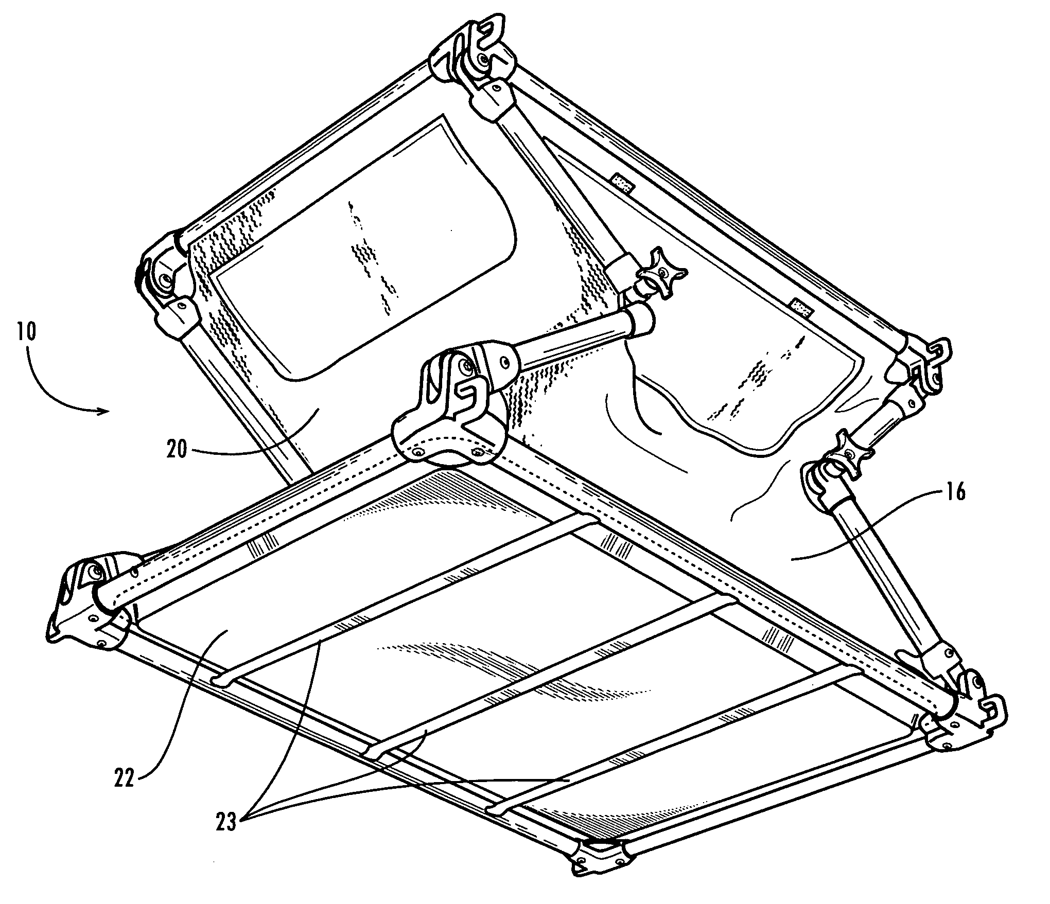
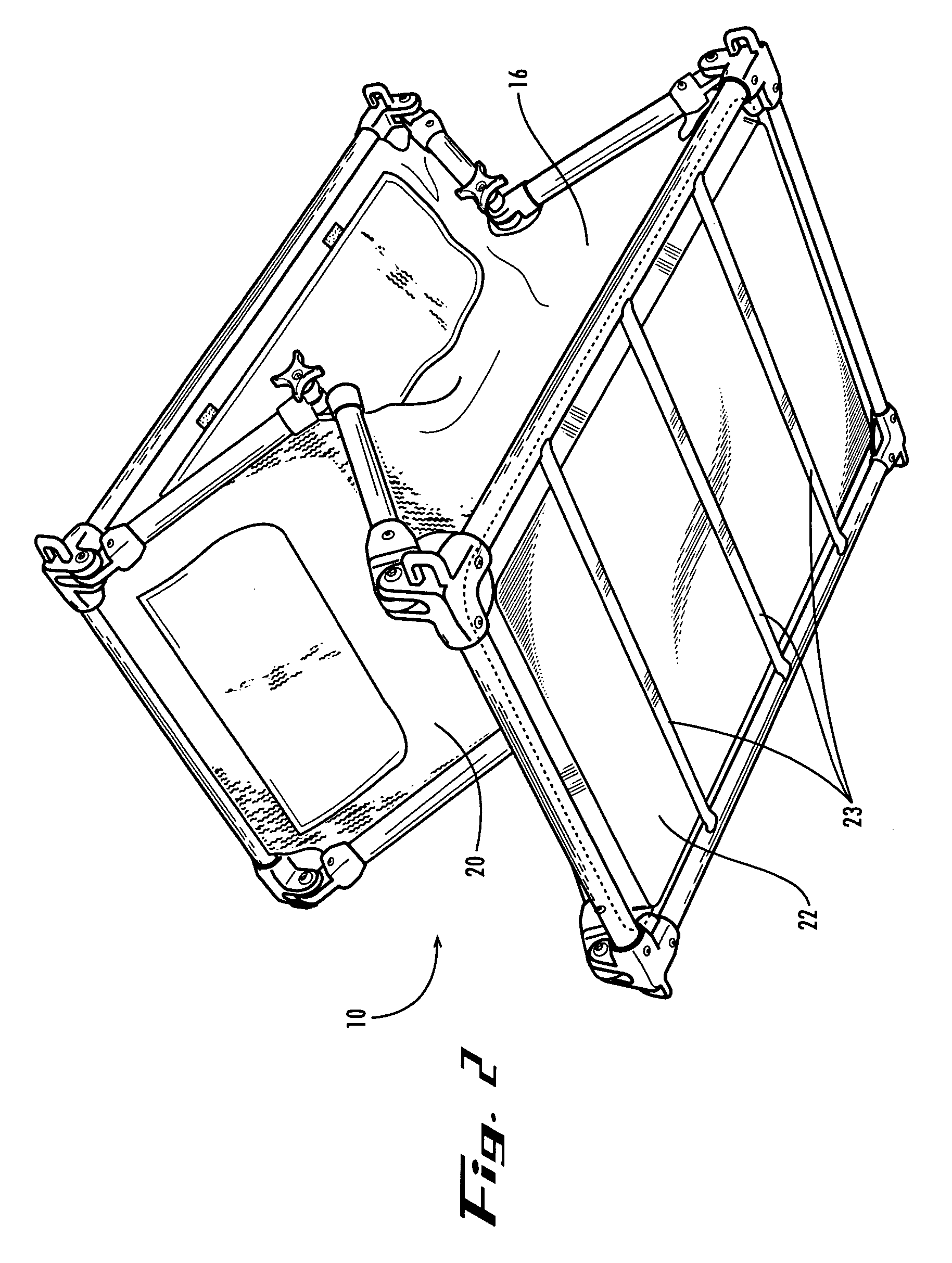
[0045] As shown in FIGS. 2 and 3, the pet housing 10 is preferably collapsible. To collapse the housing 10, the user preferably loosens the knee joints 50 by rotating the lock-nut knobs counterclockwise or otherwise disengaging the knee joint locking features. Once all of the knee joints 50 have been loosened, the user then gently pushes the top panel 12 towards the bottom panel 22 (or vice versa) until the housing 10 collapses into a generally flat, rectangular structure. The knee joints 50 may be pushed inwardly to initiate collapsing of the device. When the housing 10 is fully collapsed, the knee joints 50 are all in their fully closed or collapsed position. In an example embodiment, the housing 10 folds to about six inches flat (i.e., the distance between the top panel12 and the bottom panel 22 in a closed configuration is about six inches). In alternate embodiments, the knee and corner joints can be omitted, and a lightweight non-collapsible pet home or carrier will be provided.
[0046] When the housing 10 is collapsed, it can be stored in a carrying case or a carrier 140, as depicted in FIG. 11. The carrying case 140 has an opening that can be closed with a zipper or other fastener(s) and one or more carrying handles 142. The case 140 preferably also has a pocket 144 for carrying ropes or cords, such as bungee cords, for securing the housing 10 to a structure. The pocket 144 can be located on the exterior of the case 140, as depicted, or the pocket 144 can be located on the interior of the case 140. Additionally, the case 140 can have multiple pockets, some of which are located on the interior of the case and some of which are located on the exterior of the case.
[0047] While the invention has been described with reference to preferred and example embodiments, it will be understood by those skilled in the art that a variety of modifications, additions and deletions are within the scope of the invention, as defined by the following claims.