
Heavy load pneumatic tire

Active Publication Date: 2005-10-20
TOYO TIRE & RUBBER CO LTD
View PDF9 Cites 40 Cited by
  • Summary
  • Abstract
  • Description
  • Claims
  • Application Information

AI Technical Summary

Benefits of technology

[0021]FIG. 4 are explanatory views of an essential portion for explaining the effect of the invention;
[0022]FIG. 5 is a partially cutaway perspective view of a preferable example of the heavy load pneumatic tire of the invention;
[0023]FIG. 6 are plan views of an essential portion of another example of a closed sipeing of the invention;
[0024]FIG. 7 are side views of an essential portion showing another example of a projecting stripe of the invention; and
[0025]FIG. 8 is a developed view of one example of a tread portion of a conventional heavy load pneumatic tire.DESCRIPTION OF THE PREFERRED EMBODIMENTS
[0026] Embodiments of the present invention will be explained with reference to the drawings below. FIG. 1 is a sectional view of a half meridian of one example of a heavy load pneumatic tire of the present invention, and FIG. 2 is a developed view of a tread portion of the tire.

Problems solved by technology

The heavy load pneumatic tire provided with the rib pattern is superior to a tire having a block pattern in wear resistance, but has a problem that only an edge of the rib is locally unevenly worn in the circumferential direction, i.e., a river wear is prone to be generated.
However, in order to effectively lower the rigidity by the sipeings, it is necessary to elongate the sipeing, there is an adverse effect that a crack is generated in the sipeing end by input from a road surface, and there is a problem that the irregular wear resistance is deteriorated, the appearance is deteriorated and the like.
On the other hand, there is a known tire in which a bottom surface of a main groove of a tire tread portion is provided with a projecting stripe, but this tire can not effectively prevent the river wear from generating due to the following reasons.
Since the height of the projecting stripe is low and the width thereof is too wide, it is difficult to prevent the river wear generation while preventing the crack in the grove bottom or stone-biting.
However, since the groove provided with the projecting stripe is a wide main groove having the groove width greater than the groove depth, the rigidity enhancing effect obtained by providing the projecting stripe becomes low, and it is difficult to effectively prevent the river wear generation.
However, since the groove bottom is provided with a simply corrugated projecting stripe, there is a problem that the river wear can not effectively be prevented.

Method used


Image

  • Heavy load pneumatic tire
  • Heavy load pneumatic tire
  • Heavy load pneumatic tire

Examples


example 1 (

Conventional Example 1 (Rib Pattern having No Sipeing)

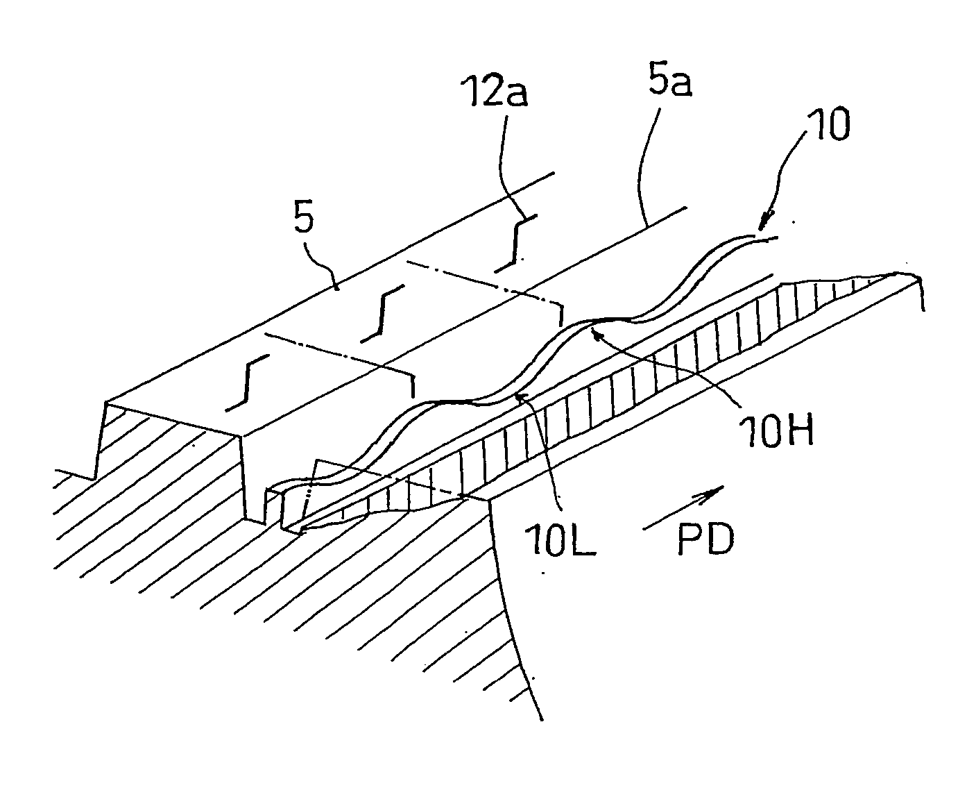
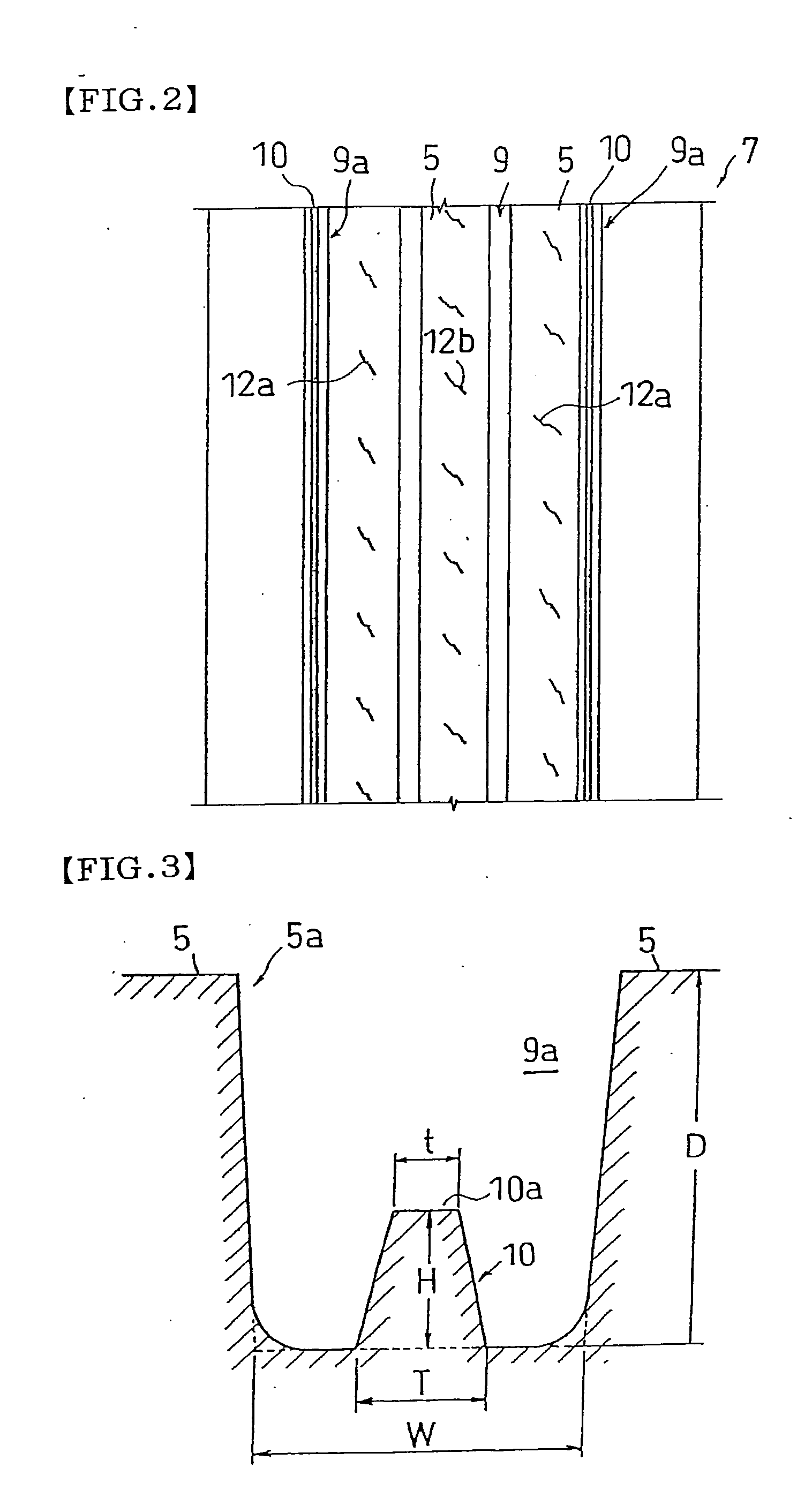
[0061] In the rib pattern shown in FIG. 2, normal heavy load pneumatic tires (size: 295 / 75R22.5) having the same tread pattern except that a projecting stripe was not formed were prepared, and the above evaluation was carried out. The depth D of the main groove is 15 mm, the groove bottom width W of the main groove is 9 mm (these values are the same in the subsequent tests). The groove width of the closed sipeing is 0.6 mm, the length thereof is 10 mm, and the interval pitch is 35 mm, a distance to the rib edge is 9.5 mm, the inclination angle with respect to the circumferential direction is about 30° (these values are the same in the subsequent tests).

example 2 (

Conventional Example 2 (Rib Pattern having Sipeing)

[0062] In the rib pattern shown in FIG. 8, normal heavy load pneumatic tires (size: 295 / 75R22.5) of a tread pattern (groove length of sipeing provided in the rib edge is 4 mm, the groove depth is 15 mm, the groove pitch is 4 mm) were prepared, and the above-described evaluation was carried out.

Example of the Present Invention 1

[0063] In the rib pattern shown in FIG. 2, normal heavy load pneumatic tires (size: 295 / 75R22.5) in which size of the projecting stripe was set to a value shown in Table 1 were prepared, and the above-described evaluation was carried out. Table 1 shows a result thereof. The sipeing provided on the rib edge of the central rib is the same as that of the conventional example 2 (the conventional example 1, other examples of the present invention, reference examples and comparative examples have the same sipeings).

TABLE 1ConventionalExample of theexamplepresent invention121T / W——0.4H / D——0.4t / T——0.9Irregular Wear...

reference examples 1 and 2

[0065] In the rib pattern shown in FIG. 2, normal heavy load pneumatic tires (size: 295 / 75R22.5) in which the size of the projecting stripe was set to a value shown in Table 2 were prepared, and the above evaluation was carried out. Table 2 shows a result of the evaluation.

TABLE 2ConventionalReferenceExample of the presentReferenceexampleexampleinventionexample1212132T / W——0.20.30.40.50.6H / D——0.40.40.40.40.4t / T——0.90.90.90.90.9Irregular100109108113117121124WearresistanceCrack inAbsenceAbsenceAbsencePresenceAbsenceAbsencePresencethegroovebottom


PUM


Abstract

The present invention provides a heavy load pneumatic tire capable of effectively preventing a river wear from generating while preventing a crack or a stone-biting from generating in a sipeing end. In a heavy load pneumatic tire in which a tread portion has a rib pattern formed with ribs divided by main grooves which are continuous in a circumferential direction of the tire, at least one of the main grooves that is located on the outermost side in a widthwise direction of the tire is provided at its groove bottom with a projecting stripe which is continuous in the circumferential direction of the tire, and the ribs adjacent to an inner side of the main groove are provided with closed sipeings arranged at substantially constant distances from each other.

Description

BACKGROUND OF THE INVENTION [0001] 1. Field of the Invention [0002] This invention relates to a heavy load pneumatic tire in which a tread portion has a rib pattern formed with ribs divided by main grooves which are continuous in a tire circumferential direction. [0003] 2. Description of the Related Art [0004] Conventionally, as a tread pattern formed on a tread portion of a heavy load pneumatic tire, there is a known rib pattern formed with ribs divided by a main groove which is continuous in a tire circumferential direction. The heavy load pneumatic tire provided with the rib pattern is superior to a tire having a block pattern in wear resistance, but has a problem that only an edge of the rib is locally unevenly worn in the circumferential direction, i.e., a river wear is prone to be generated. [0005] Concerning details of generation process of this river wear, it is considered that a fine step is first generated in a rib end by a lateral force caused during running of the tire, ...

Claims


Application Information

Patent Timeline
IPC IPC(8): B60C11/04B60C11/13B60C11/12
CPCB60C11/042B60C11/12Y10S152/01Y10S152/03Y10S152/901B60C11/047B60C2011/1254B60C2200/06
Inventor MIYAKE, AKINORI
Owner TOYO TIRE & RUBBER CO LTD
Features
  • Generate Ideas
  • Intellectual Property
  • Life Sciences
  • Materials
  • Tech Scout
  • Unparalleled Data Quality
  • Higher Quality Content
  • 60% Fewer Hallucinations
Learn More