Method and apparatus for detecting a presence prior to collision

a technology of collision and detection method, applied in the field of artificial or computer vision systems, can solve the problems of uneven depth image generation and multiple resolution disparities, and achieve the effect of avoiding collision and avoiding collision

Inactive Publication Date: 2005-10-20
SARNOFF CORP +1
View PDF7 Cites 74 Cited by
  • Summary
  • Abstract
  • Description
  • Claims
  • Application Information

AI Technical Summary

Problems solved by technology

Thus, the depth image generated may not correspond smoothly with each multiple resolution disparity image.

Method used


Image

  • Method and apparatus for detecting a presence prior to collision
  • Method and apparatus for detecting a presence prior to collision
  • Method and apparatus for detecting a presence prior to collision

Examples


Embodiment Construction

[0014] The present invention discloses in one embodiment method and apparatus for classifying an object in a region of interest based on one or more features of the object. Detection and classification of pedestrians, vehicles, and other objects are important, e.g., for automotive safety devices, since these devices may deploy in a particular fashion only if a target of the particular type (i.e., pedestrian or car) is about to be impacted. In particular, measures employed to mitigate the injury to a pedestrian may be very different from those employed to mitigate damage and injury from a vehicle-to-vehicle collision.

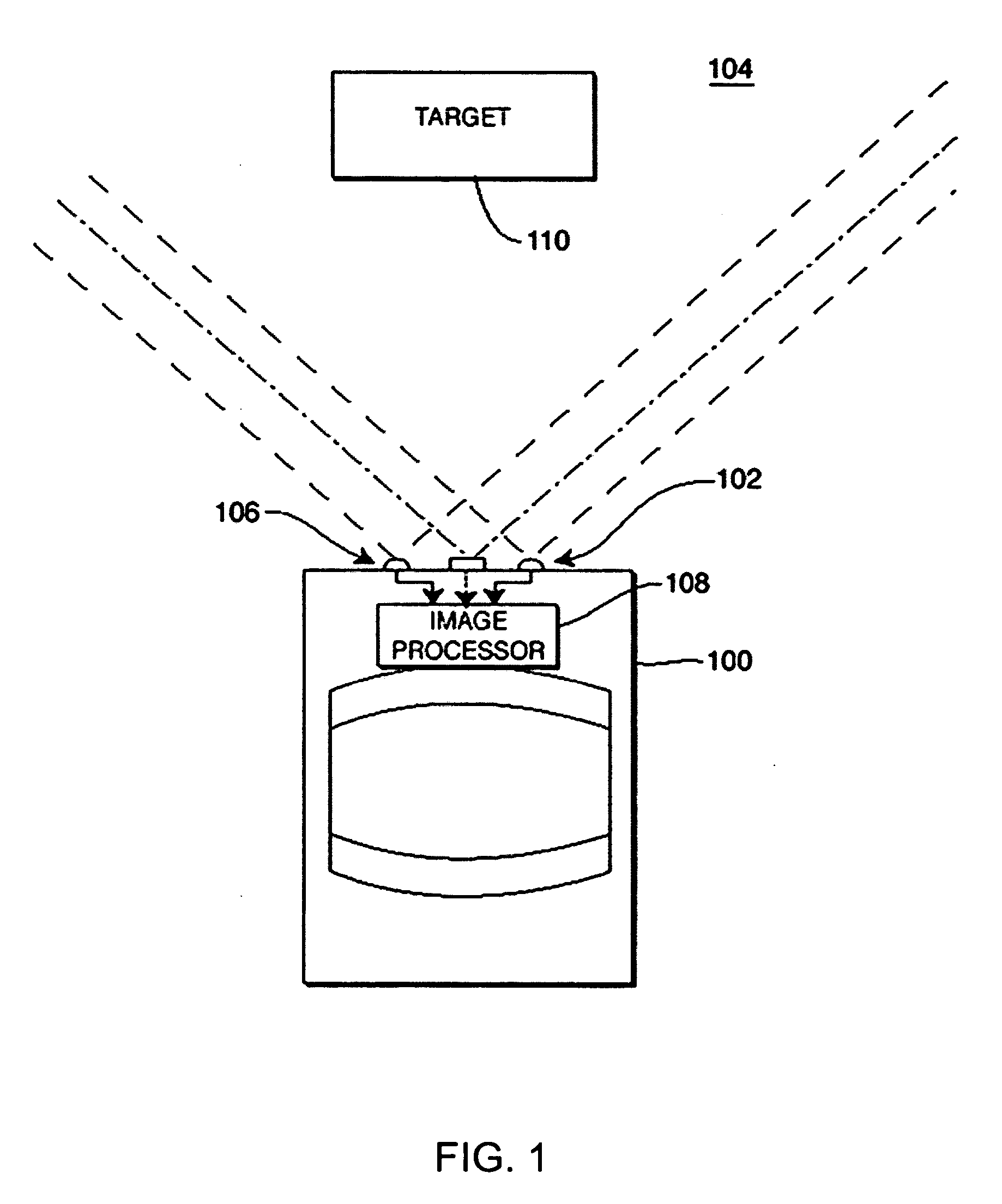
[0015]FIG. 1 depicts a schematic diagram of a vehicle 100 having a target differentiation system 102 that differentiates a pedestrian (or pedestrians) 110 within a scene 104 that is proximate the vehicle 100. It should be understood that target differentiation system 102 is operable to detect pedestrians, automobiles, or other objects. While in the illustrated embodimen...


PUM


Abstract

A method and apparatus for detecting a target in an image is disclosed. A plurality of depth images is provided. A plurality of target templates is compared to at least one of the plurality of depth images. A scores image is generated based on the plurality of target templates and the at least one depth image.

Description

CROSS-REFERENCE TO RELATED APPLICATIONS [0001] This application claims the benefit of U.S. provisional patent application No. 60 / 549,186 filed, Mar. 2, 2004, which is herein incorporated by reference.BACKGROUND OF THE INVENTION [0002] 1. Field of the Invention [0003] The present invention relates to artificial or computer vision systems, e.g. vehicular vision systems. In particular, this invention relates to a method and apparatus for detecting objects in a manner that facilitates collision avoidance. [0004] 2. Description of the Related Art [0005] Collision avoidance systems utilize a sensor system for detecting objects in front of an automobile or other form of vehicle or platform. In general, a platform can be any of a wide range of bases, including a boat, a plane, an elevator, or even a stationary dock or floor. The sensor system may include radar, an infrared sensor, or another detector. In any event the sensor system generates a rudimentary image of the scene in front of the ...

Claims


Application Information

Patent Timeline
Patent Type & Authority Applications(United States)
IPC IPC(8): B60Q1/00B62J3/00B62J6/00G06K9/00G06K9/32G06K9/54G06K9/60G06K9/62
CPCG06K9/00805G06K9/3241G06V20/58G06V10/255
Inventor HIRVONEN, DAVIDCAMUS, THEODORE ARMANDSOUTHALL, JOHN BENJAMINMANDELBAUM, ROBERT
Owner SARNOFF CORP
Why Eureka
Try Eureka