Distributed object classification

a technology of distributed objects and classification, applied in the computer field, can solve problems such as user confusion, difficulty and confusion, and structure, and achieve the effect of improving user experience and improving user experien

Inactive Publication Date: 2005-10-20
MICROSOFT TECH LICENSING LLC
View PDF25 Cites 33 Cited by
  • Summary
  • Abstract
  • Description
  • Claims
  • Application Information

AI Technical Summary

Benefits of technology

[0010] The distributed classification system and method of the subject invention provides a multitude of advantages. For instance, users have a single place to go to maintain common data structures like their project classifications. Additionally, any common data that can be expressed as a hierarchy or list can be maintained through one common mechanism.

Problems solved by technology

This makes it difficult and confusing for users as they must try and understand a plurality of different programming implementations.
The problem is that the project classification hierarchy can vary from company to company, and in many instances between project types within a single company.
The individual classification mechanisms and structures lead to user confusion due at least in part to the fact that they must understand the inner workings of many classification mechanisms.

Method used


Image

  • Distributed object classification
  • Distributed object classification
  • Distributed object classification

Examples


example

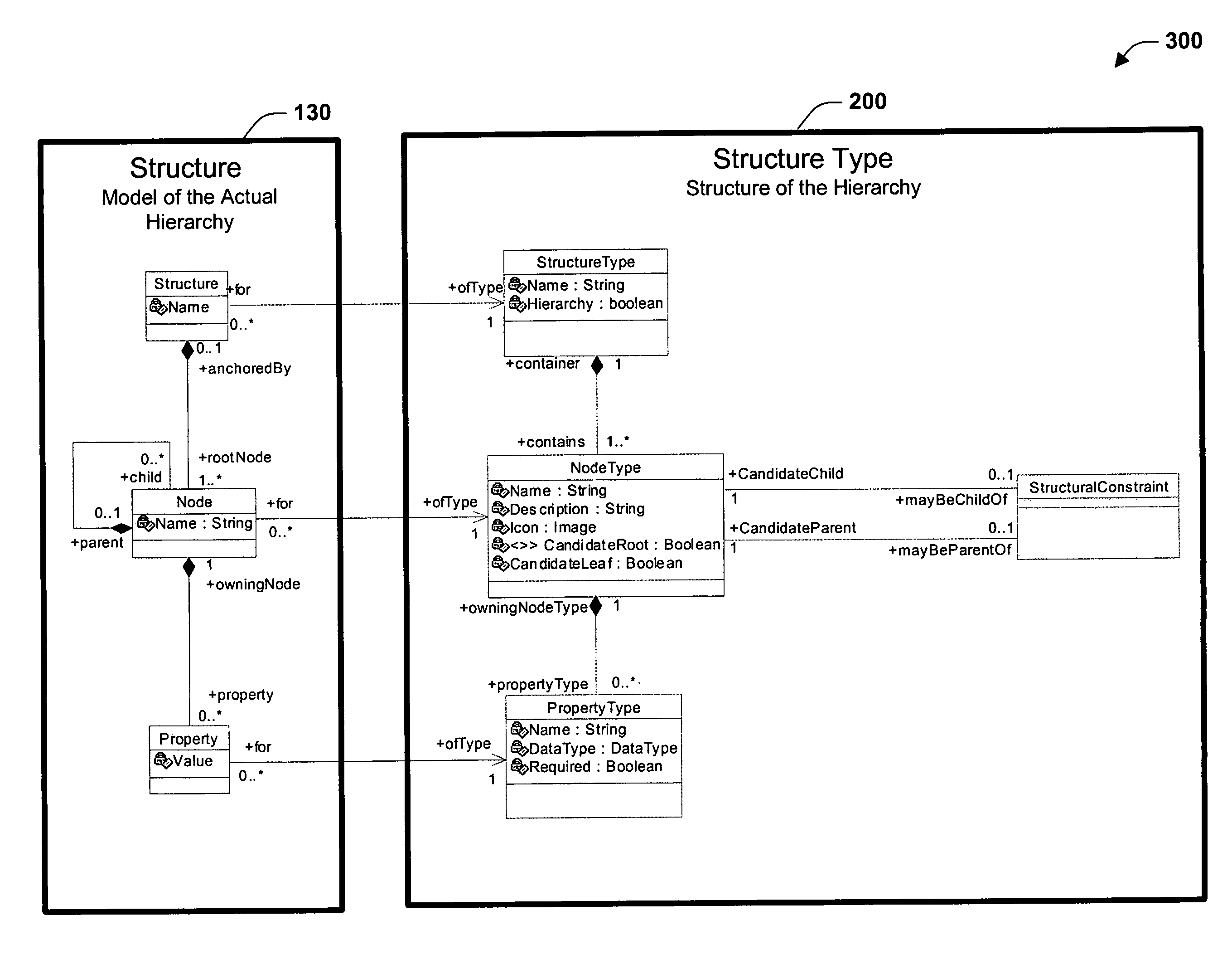
[0058] The following example utilizes instance diagrams to illustrate how specific instances of the classes described in the preceding sections are employed to represent a structure. To start, assume that we want two structures (FIGS. 4-5) organized as follows: [0059] 1. Project Lifecycle hierarchy that is made up of a set of decomposing Life Cycle Item nodes. FIG. 4 illustrates an example of part of a Project Lifecycle hierarchy 400. [0060] 2. A Project Model hierarchy that involves nodes of three types: (a) Organizational Unit; (b) Component; and (c) Feature Area. [0061] 3. The relationships between the nodes of various types in the Project Hierarchy follow these rules: [0062] a. The top nodes in the hierarchy should be Organizational Units. [0063] b. Each child of an Organizational Unit can be one of the following: [0064] i. A subordinate Organizational Unit; [0065] ii. A Component; or [0066] iii. A Feature Area. [0067] c. Each child of a Component can be either: [0068] i. A subo...


PUM


Abstract

The present invention provides a system and method for unrelated tools to categorized elements they control according to a common centrally managed classification scheme. The invention also provides a mechanism for storing, retrieving, and modifying classifying information. Users of unrelated tools that employ the subject invention see a single and consisted user interface.

Description

TECHNICAL FIELD [0001] The present invention relates generally to computers and more particularly toward optimizing application interactions. BACKGROUND [0002] Individuals designing and architecting systems typically utilize a variety of tools, each designed for a particular purpose. Although conventional integrated development environments have gone a long way toward integrating a variety of tools that deal with part of the process, sometimes there are other tools that are needed that are not part of the integrated development environment. This makes it difficult and confusing for users as they must try and understand a plurality of different programming implementations. [0003] For example, the organization of an enterprise development project enables team members to communicate meaningful information about the state of a project's progress. It also provides a system of grouping software artifacts in some logical fashion. The problem is that the project classification hierarchy can...

Claims


Application Information

Patent Timeline
Patent Type & Authority Applications(United States)
IPC IPC(8): G06F17/30
CPCG06F17/30598G06F16/285
Inventor MINIUM, DENNIS W. JR.ESSARY, BILL S.FU, XIONGJIAN
Owner MICROSOFT TECH LICENSING LLC
Why Eureka
Try Eureka