Method and device for compensating for shadows in digital images

Active Publication Date: 2005-10-27
BAYERISCHE MOTOREN WERKE AG
View PDF7 Cites 2 Cited by
  • Summary
  • Abstract
  • Description
  • Claims
  • Application Information

AI Technical Summary

Benefits of technology

[0015] Basically, a large number of suitable control modes of image taking and illumination are contemplated. However, a method was found to be particularly advantageous which is distinguished in that three individual images are taken for computing a result image, in which case two light sources are controlled such that, when a first individual image is taken, the first light source illuminates the scene with a first luminous intensity and the second light source illuminates the scene with a second luminous intensity differing from the first; during the taking of a second individual image, the first light source illuminates the scene with the second luminous intensity and the second light source illuminates the scene with the first luminous intensity; and, during the taking of a third individual image, both light sources each illuminate the scene with the second luminous intensity. As a result, the offsetting of the individual images with respect to one another becomes very easy. On the one hand, only a small number of individual images, specifically three, is required. On

Problems solved by technology

This task, which is simple for the human brain, presents considerable difficulties to automa

Method used


Image

  • Method and device for compensating for shadows in digital images
  • Method and device for compensating for shadows in digital images

Examples


Example

DETAILED DESCRIPTION OF THE DRAWINGS

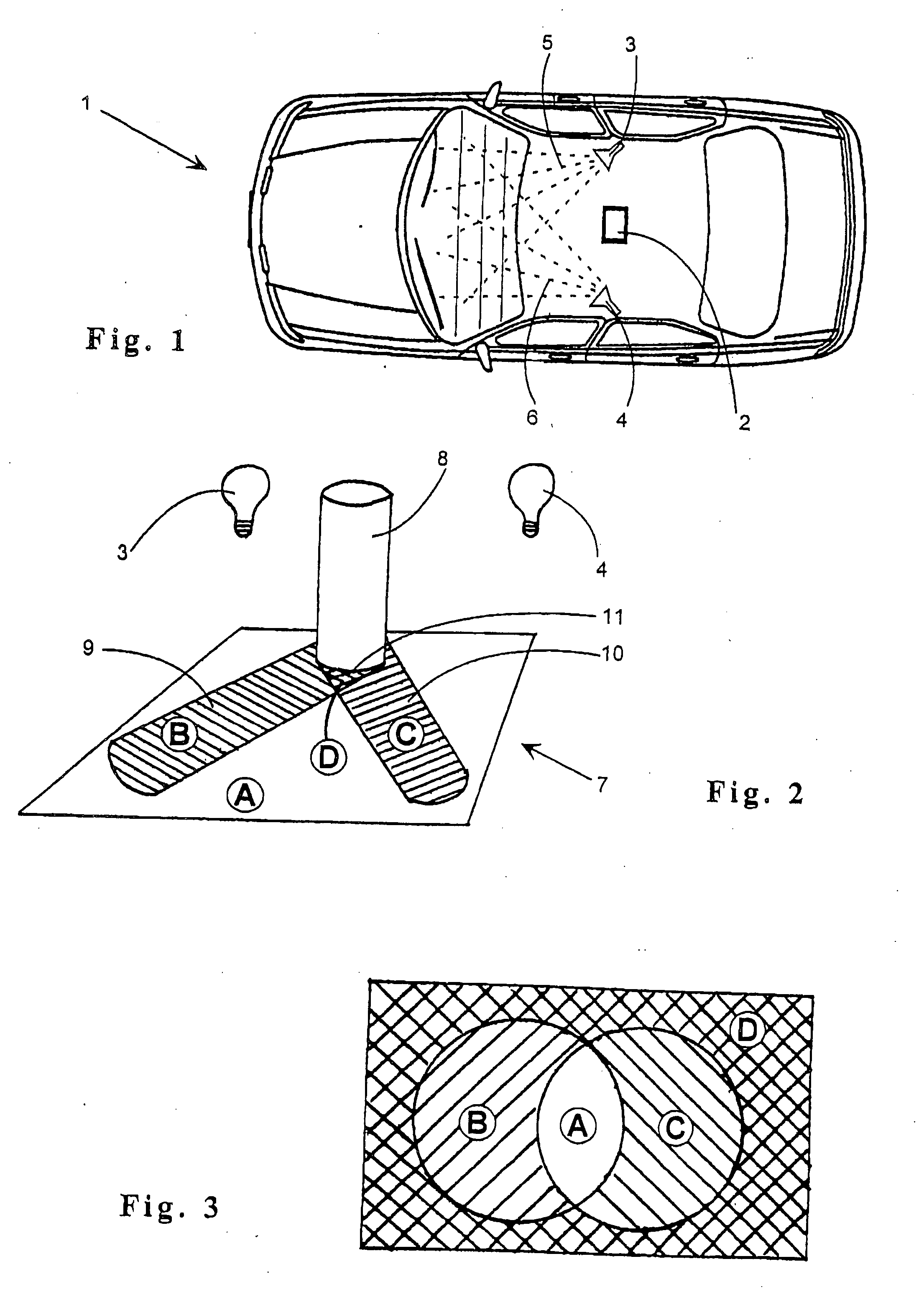
[0026]FIG. 1 is a top view of a motor vehicle 1, in which an image sensor 2 is arranged in central position on the roof ceiling, which image sensor 2 at least partially detects the interior of the vehicle 1 in the close IR spectral region and in a known manner produces digital images thereof. The image sensor 2 is controlled by control devices which are not shown and supplies its image data to an also not shown data processing system. Both devices can be integrated, for example, in an on-board computer which, as a rule, is present anyhow in modem vehicles. Naturally, the utilization of independent specialized units is also contemplated.

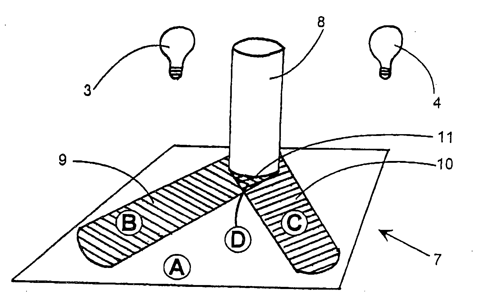
[0027] One light-emitting diode 3, 4 respectively or a group of light-emitting diodes are arranged in the area of the B-columns of the vehicle and emit light 5, 6 in the close IR region into the interior of the vehicle. Like the image sensor 2, which detects the illumination light of the diodes reflected by the sc...


PUM


Abstract

The invention relates to a method for generating a computed digital image of a scene, which can be illuminated with different luminous intensities at a first illumination angle by a first light source. An image sensor records a number of individual images of the scene under different lighting conditions, and these images are set against one another in a pixel-by-pixel manner in a data processing device in order to generate a resulting image. The invention is characterized in that at least one additional light source is provided by means of which the scene can be illuminated at an illumination angle that is different from the illumination angle of the first light source. The different lighting conditions when recording the individual images are obtained by various combinations of luminous intensities of the first and of the at least one other additional light source. The invention also relates to a device for carrying out the inventive method.

Description

CROSS REFERENCE TO RELATED APPLICATIONS [0001] This application is a continuation of International Patent Application No. PCT / EP2003 / 010224, filed Sep. 12, 2003, designating the United States of America, and published in German as WO 2004 / 040515 A1, the entire disclosure of which is incorporated herein by reference. Priority is claimed based on German Patent Application No. 102 50 705.8, filed Oct. 31, 2002.BACKGROUND AND SUMMARY OF THE INVENTION [0002] The invention relates to a method of producing a computed digital image of a scene, which can be illuminated with different luminous intensities at a first illumination angle by a first light source. A plurality of individual images of the scene under different lighting conditions are taken by an image sensor and are offset against one another in a pixel-by-pixel manner in a data processing device for generating a resultant image. [0003] The invention also relates to a device for producing a computed digital image, including a first ...

Claims


Application Information

Patent Timeline
IPC IPC(8): G01S17/04G06T5/50G06T7/00
CPCG01S17/026G06T7/0002G06T5/50G01S17/04
Inventor EISENMANN, LUTZKOCH, CARSTENYOON, JASON JEONG-SUK
Owner BAYERISCHE MOTOREN WERKE AG
Why Eureka
Try Eureka