Image sensor and electronic device having the same

Active Publication Date: 2019-09-19
CANON KK
View PDF0 Cites 1 Cited by
  • Summary
  • Abstract
  • Description
  • Claims
  • Application Information

AI Technical Summary

Benefits of technology

[0005]The present invention provides an image sensor that can easily obtain an image in wh

Problems solved by technology

However, the configuration disclosed in Japanese Patent Laid-Open No. 2010-193524 requires that the i

Method used


Image

  • Image sensor and electronic device having the same
  • Image sensor and electronic device having the same
  • Image sensor and electronic device having the same

Examples


Example

First Embodiment

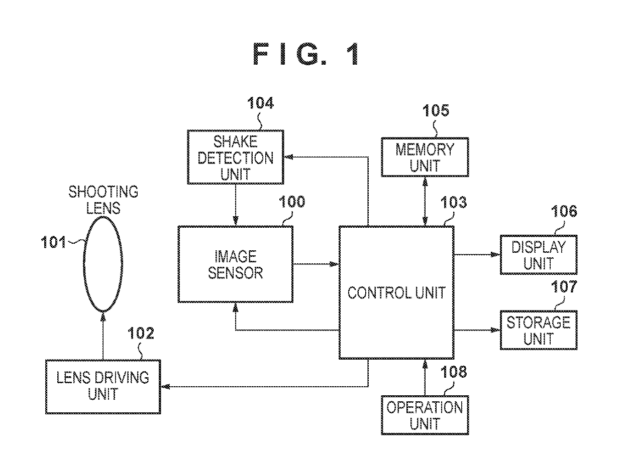
[0021]FIG. 1 is a block diagram illustrating an example of the overall functional configuration of an image capture apparatus according to the first embodiment of the present invention. A shooting lens 101 includes a lens group and an aperture stop, and forms an optical image of an object on an image capturing surface of an image sensor 100. The shooting lens 101 includes a mechanism for driving a movable lens, the aperture stop, and the like (e.g., a motor or an actuator). The aperture stop may function as a mechanical shutter.

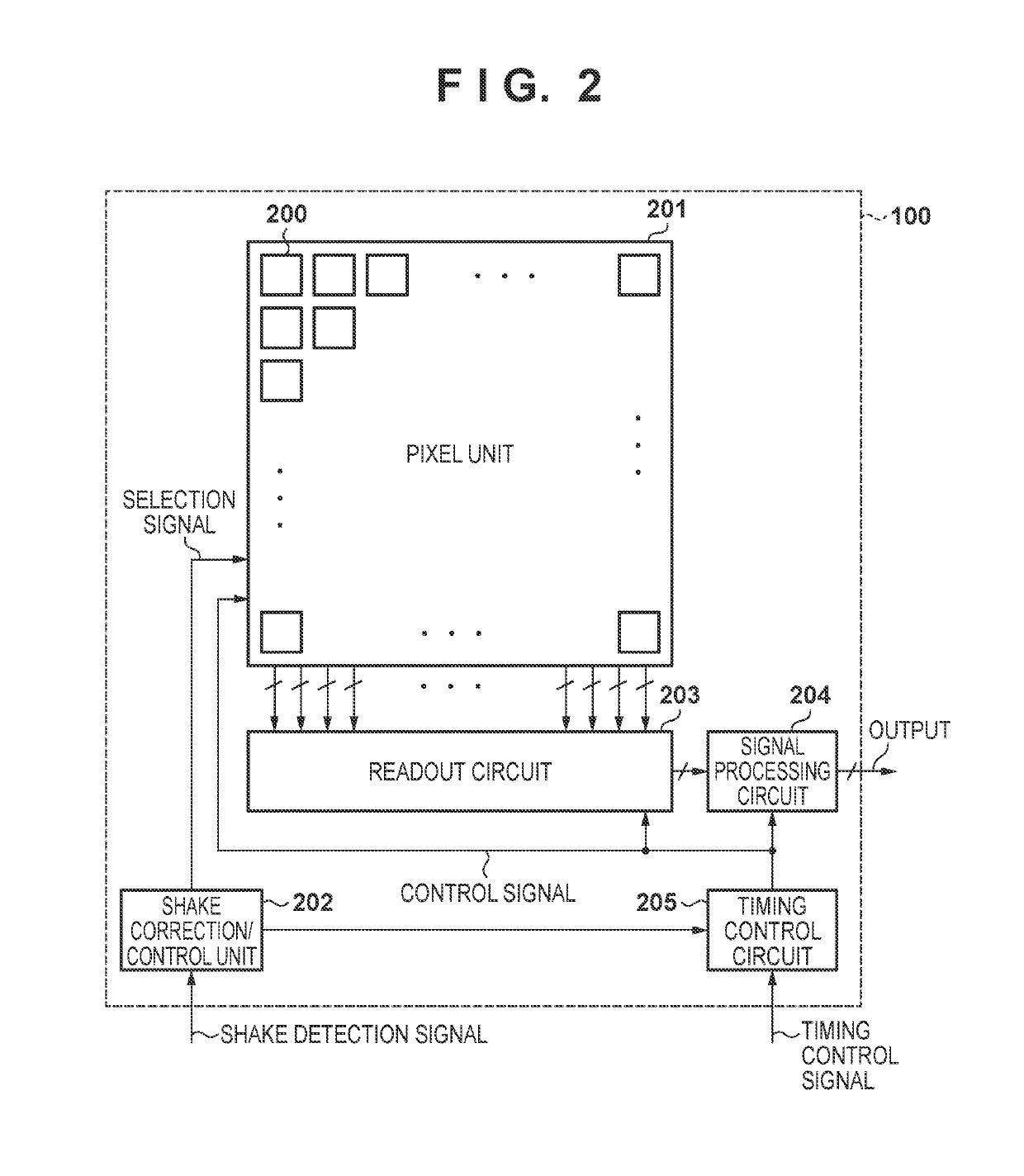
[0022]The image sensor 100 includes a plurality of pixels, and the optical image formed by the shooting lens 101 is converted into image data by photoelectric conversion units included in the pixels. In the present embodiment, the image sensor 100 employs photoelectric conversion units capable of detecting single photons, and can therefore obtain pixel values directly as digital values without A / D conversion. The image sensor 100 will be descr...

Example

Second Embodiment

[0073]Next, a second embodiment of the present invention will be described. The following will primarily describe areas that are different from the first embodiment. The present embodiment differs from the first embodiment in that the image sensor includes the function of the shake detection unit 104, and the configuration of the pixels is different.

[0074]An example of the configuration of an image sensor 900 according to the present embodiment will be described with reference to FIG. 8. Of the constituent elements in the image sensor 900, a signal processing circuit 905 and a timing control circuit 906 are the same as the circuits in the first embodiment that have the same names.

[0075]A readout circuit 903 is the same as that in the first embodiment, in terms of reading out pixel signals from an active pixel region in a pixel unit 902 and outputting the signals to the signal processing circuit 905, at the end of the obtainment of one frame's worth of an image. In a...


PUM


Abstract

An image sensor that obtains an image in which shake is corrected, while at the same time suppresses an increase in the circuit size, is disclosed. The image sensor has a plurality of pixels. Each of the plurality of pixels includes a light-sensitive element that detects the incidence of single photons; and a counter that counts a pulse contained in a signal. The image sensor further comprises a control unit that, on the basis of detected shake, switches a signal of the light-sensitive element supplied to the counter in a pixel, or replaces a count value of the counter of the pixel with a count value of the counter in another pixel.

Description

BACKGROUND OF THE INVENTIONField of the Invention[0001]The present invention relates to an image sensor and an electronic device having the same.Description of the Related Art[0002]Electronic shake correction is known as an existing method for correcting image shake produced when an image capture apparatus moves. Electronic shake correction does not require mechanical driving, and thus has advantages over optical shake correction in terms of miniaturization and reduced costs.[0003]Generating a high-dynamic range image by combining multiple images is also a known technique (Japanese Patent Laid-Open No. 2010-193524). Japanese Patent Laid-Open No. 2010-193524 discloses registering images when combining the images, to correct image shake in the resulting composite image.[0004]However, the configuration disclosed in Japanese Patent Laid-Open No. 2010-193524 requires that the image sensor be provided with frame memory for combining the images, which increases the circuit size. Image reso...

Claims


Application Information

Patent Timeline
IPC IPC(8): H04N5/232
CPCH04N5/2327H04N5/23258H04N5/23254H04N23/6811H04N23/6812H04N23/684
Inventor KUMAKI, SATOSHIKOBAYASHI, HIROKAZU
Owner CANON KK
Why Eureka
Try Eureka