Radio Communication Terminal

a technology of radio communication terminal and terminal, which is applied in the direction of impedence matching network, liquid/fluent solid measurement, instruments, etc., can solve the problems of low efficiency under high voltage in the initial discharge stage, inability to make the usable time of the terminal sufficiently long, and deterioration of the optimal value of the efficiency. , to achieve the effect of enhancing the usable time of the terminal, reducing the voltage, and reducing the voltag

Inactive Publication Date: 2006-03-09
SONY MOBILE COMM INC
View PDF5 Cites 19 Cited by
  • Summary
  • Abstract
  • Description
  • Claims
  • Application Information

AI Technical Summary

Benefits of technology

[0044] According to the embodiment of the present invention, switching between the matching circuits is performed corresponding to the battery voltage. Thereby, the circuit efficiency can be enhanced in a wide range of battery discharge voltages, consequently enabling the usable time of the terminal to be increased. Accordingly, a large capacity secondary battery that exhibits a large voltage drop can be effectively utilized.
[0045] In addition, the power amplifiers having two end voltages are provided, and are switchably used corresponding to the battery voltage. Thereby, the circuit efficiency can be enhanced in the overall range of battery discharge voltages, consequently making it possible to increase the usable time of the terminal.
[0046] The present invention is adapted to the first and second power amplifiers contained in the multi-band terminal, whereby the usable time of the terminal can be increased without enhancing the circuit scale.
[0047] Even in the configuration wherein the power amplifiers different in the power source voltage performance depending on the to-be used band are used, since control is performed in accordance with the two end voltages, the battery can be effectively used.
[0048] Even when one of the radio bands is disabled for use during communication, the measure is taken to perform radio-band switching corresponding to the decrease in the battery voltage. This enables continual use of the terminal without causing communication to be discontinued.

Problems solved by technology

In comparison, in the case the large-capacity secondary battery is used for the power source voltage of the previous power amplifier, the end voltage has to a half level of discharge of the battery, so that the battery cannot be used to the end, so that the usable time of the terminal cannot be made to be sufficiently long.
In addition, in the case that the power amplifier is designed to be optimized at a relatively small operation voltage, the efficiency under a high voltage in an initial discharge stage is low, but also the optimal value itself of the efficiency deteriorates.
Consequently, even with the large-capacity secondary battery being used, the usable time of the terminal cannot be made to be sufficiently long.

Method used


Image

  • Radio Communication Terminal
  • Radio Communication Terminal
  • Radio Communication Terminal

Examples


first embodiment

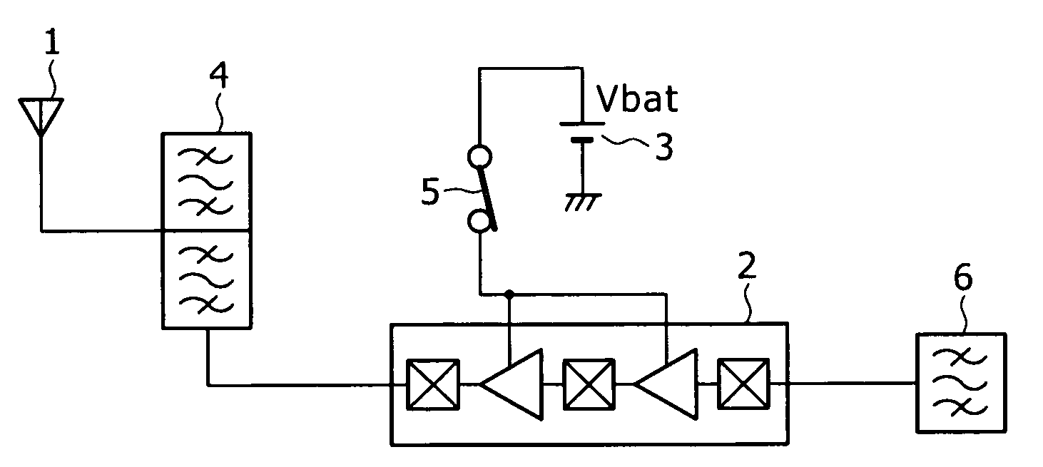
[0065]FIG. 7 is a block diagram a communication terminal according to the present invention.

[0066] A power amplifier 2 has a configuration including input terminal 10, an output terminal 11, a switch signal input terminal 12, first stage input matching circuit 16, a first stage amplifier section 13, an inter-stage matching circuit 17, a last stage amplifier section 14, a first last-stage output matching circuit 19, a second last-stage output matching circuit 18, and a matching switch section 20.

[0067] The first last-stage output matching circuit 19 is optimized to be capable of outputting a maximum transmission power with high efficiency in the vicinity of an average discharge voltage (Vl) of a battery. The second last-stage output matching circuit 18 is optimized to be capable of outputting a maximum transmission power with high efficiency under a relatively low power source voltage in the discharge voltage characteristics of the battery.

[0068] A battery voltage monitor section 3...

fourth embodiment

[0080]FIG. 10 is a block diagram of a communication terminal according to the present invention. The same reference characters identify the same components as those in the embodiments described above, and duplicated descriptions thereof will be omitted herefrom.

[0081]FIG. 10 is the case of adaptation to a transmit section corresponding to dual modes (or, multi-modes) using a plurality of radio bands A and B. The dual modes enable switchable use of communication systems different from one another. Dual modes enable switchable use of radio bands different from one another in a same system. Generally, in the dual modes, radio bands to be used in two modes are different from one another. In the radio band A, the first power amplifier 52 and the first duplexer 42 are used, whereas in the radio band B, the second power amplifier 51 and the second duplexer 41 are used. In correspondence to the radio band to be used, a switch 43 switches the connection of the antenna 1 to the transmission c...


PUM


Abstract

A radio communication terminal has a plurality of matching circuits that optimize the efficiency of a power amplifier for a range of different battery voltages. A first matching circuit optimizes the efficiency of the power amplifier for a battery voltage higher than a predetermined threshold value. A second matching circuit optimizes the efficiency of the power amplifier at a voltage lower than the threshold value. A control section compares a detection result of a battery voltage from a voltage monitor section with the threshold value, and performs switching between the plurality of matching circuits.

Description

CROSS REFERENCES TO RELATED APPLICATIONS [0001] The present invention contains subject matter related to Japanese Patent Application JP 2004-257340 filed in the Japanese Patent Office on Sep. 3, 2004, the entire contents of which being incorporated herein by reference. BACKGROUND OF THE INVENTION [0002] 1. Field of the Invention [0003] The present invention relates to a radio communication terminal to be operated by a battery, and more specifically to a radio communication terminal capable of increasing a usable time of the terminal. [0004] 2. Description of the Related Art [0005] In resent years, cellular phone terminals (each of which hereinbelow will be alternatively referred to as a “terminal”) contain a variety of applications, so that while various ways of usage are made possible, the usable time thereof is required to be increased as long as possible. Such terminals operate with a secondary battery working as a power source, so that the following three points are important to...

Claims


Application Information

Patent Timeline
Patent Type & Authority Applications(United States)
IPC IPC(8): G06F1/26
CPCH04B1/0458Y02B60/50H04B2001/045H03F1/02H03F3/24H04B1/40H03H11/28
Inventor MIZUSAWA, NISHIKI
Owner SONY MOBILE COMM INC
Why Eureka
Try Eureka