
Mobile communication network system and mobile communication method

Active Publication Date: 2005-07-28
NEC CORP
View PDF16 Cites 15 Cited by
  • Summary
  • Abstract
  • Description
  • Claims
  • Application Information

AI Technical Summary

Benefits of technology

[0019] According to the present invention, when realizing communication between mobile terminals, communication is returned at the radio access point when each mobile terminal is subordinate to the same radio access point, communication is realized by way of the access network when each mobile terminal is subordinate to the same access network, and communication is realized through the core network when each mobile terminal is subordinate to different access networks. As a result, packets no longer need to be transferred by way of external network gateways, and the efficiency of circuit use of the access network is improved.
[0024] According to the present invention, the private leased line connection between a mobile terminal and an external network can be maintained without being cut off when a mobile terminal is handed over.
[0025] According to yet another mobile communication network system of the present invention, a mobility management node is arranged within the mobile communication network, and this mobility management node is composed of a plurality of virtual mobility management nodes that have been prepared for each external network. Each of the virtual mobility management nodes is then provided with means for transmitting packets to and receiving packets from only a virtual network that has been prepared for use by a corresponding external network. Each of the mobile terminals are further provided with means for notifying positional information to the virtual mobility management node that corresponds to the external network to which that mobile terminal is connected. In addition, each of the virtual mobility management nodes is provided with: means for holding the positional information that has been reported from mobile terminals, and means for, upon receiving packets that are addressed to a mobile terminal, transferring the packets to the position that has been reported from the mobile terminal. By means of this configuration, virtual networks that have been prepared on the mobile communication network to correspond to each of the external networks can manage the positions of mobile terminals.
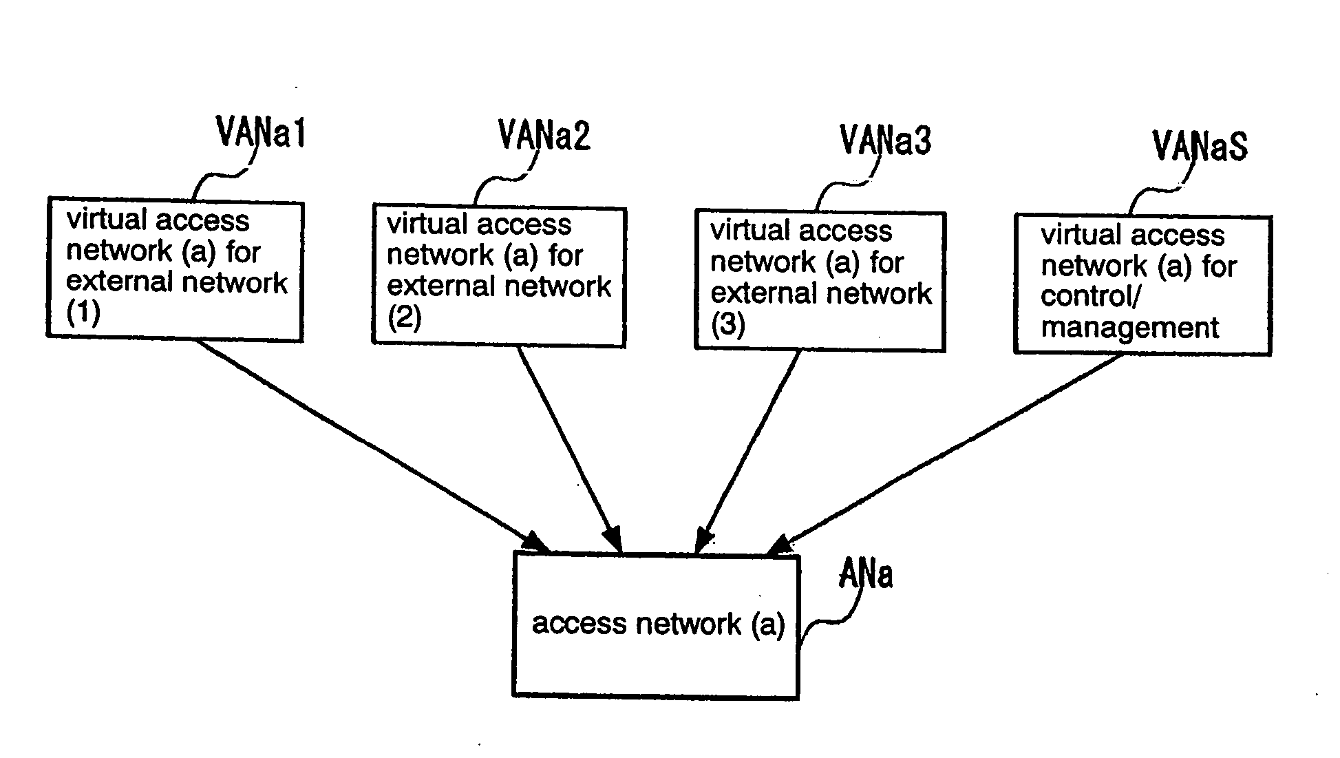
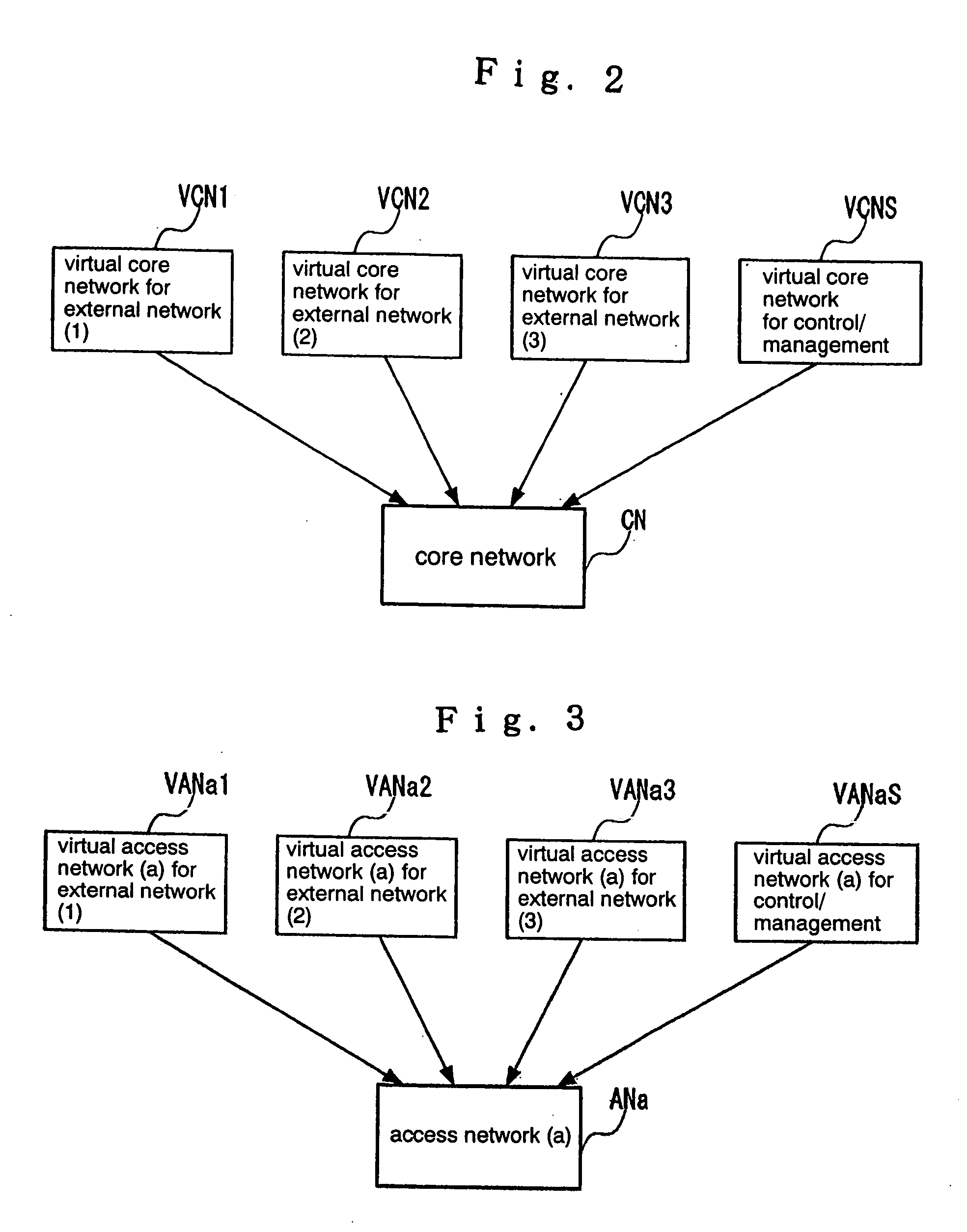
[0027] According to the present invention, virtual core networks and virtual access networks make up private networks, whereby the inconvenience of establishing a security association between mobile terminals is eliminated.
[0028] Finally, according to the present invention, communication between nodes on a mobile communication network is also protected by the virtual access networks and virtual core networks for control and management, whereby the inconvenience of establishing a security association between nodes is eliminated.

Problems solved by technology

With regard to multicast communication, as well, in the prior art, multicast packets were copied a number of times equal to the number of mobile terminals that receive the multicast packets in external network gateways and then transmitted to mobile terminals in tunnels, and the efficiency of circuit use was therefore poor.

Method used


Image

  • Mobile communication network system and mobile communication method
  • Mobile communication network system and mobile communication method
  • Mobile communication network system and mobile communication method

Examples


first embodiment

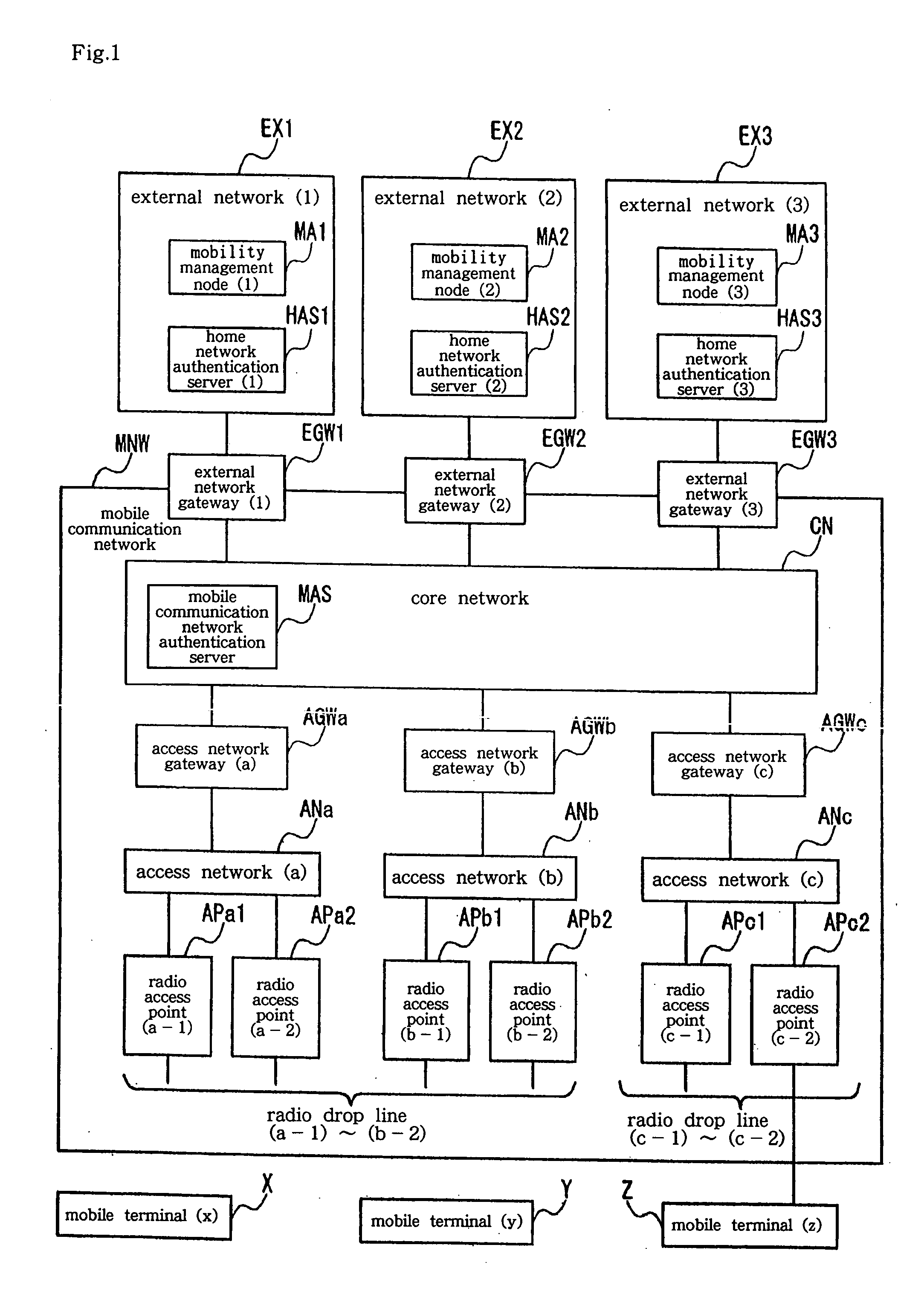
[0065] Explanation next regards the first embodiment with reference to FIG. 1. FIG. 1 shows the configuration of an overall network. The overall network is composed of: a plurality of external networks EX1, EX2, and EX3; mobile communication network MNW that is connected to these external networks; and a plurality of mobile terminals X, Y, and Z that are connected to one or more of the external networks by way of mobile communication network MNW. The number of external networks and the number of mobile terminals are not limited to any specific number.

[0066] Mobile communication network MNW is composed of: core network CN; a plurality of access networks ANa, ANb, and ANc; a plurality of radio drop lines; a plurality of wired drop lines; external network gateways EGW1, EGW2, and EGW3 that connect core network CN to the external networks; access network gateways AGWa, AGWb, and AGWc that connect core network ON to access networks; radio access points APa1, APa2, APb1, and APb2 that co...

second embodiment

[0167] Explanation next regards the second embodiment of the present invention with reference to FIG. 33. The configuration of the mobile communication network of FIG. 33 is essentially identical to that of FIG. 1, with the exception of the addition of local mobility management node LMA1 to the core network.

[0168]FIG. 34 shows the configuration of local mobility management node LMA1. Local mobility management node LMA1 is made up from: transceiver TR09, virtual core network multiplexing / separation function CMUXL, external network (1) virtual local mobility management node VLMA1, external network (2) virtual local mobility management node VLMA2, external network (3) virtual local mobility management node VLMA3, and control / management virtual local mobility management node VLMAS.

[0169] Transceiver TR09 is connected to core network CN and transmits and receives packets.

[0170] Virtual core network multiplexing / separation function CMUXL separates packets that are received as input fro...


PUM


Abstract

The mobile communication network system of the present invention is made up from a mobile communication network (MNW), a plurality of external networks (EX1-EX3), a plurality of mobile terminals (x, y, z), a plurality of gateways (EGW1-EGW3) for connecting the external networks (EX1-EX3) and mobile communication network (MNW), and a plurality of radio access points (APa1-APc2) for connecting the mobile terminals (x, y, z) to the mobile communication network (MNW). When packets are transmitted and received between mobile terminals (x, y, z) within the mobile communication network (MNW), the packets are communicated, not by way of external networks (EX1-EX3), but by way of virtual networks that correspond to each external network (EX1-EX3) that have been prepared on the mobile communication network.

Description

TECHNICAL FIELD [0001] The present invention relates to a mobile communication network system and to a mobile communication method, and more particularly to mobile communication network system and a mobile communication method in which a mobile communication network provides a private leased line connection capability between external networks and mobile terminals. BACKGROUND ART [0002] Prior art in which a mobile communication network provides a private leased line connection capability between external networks and mobile terminals includes GPRS (General Packet Radio Service), which is a mobile communication technology prescribed by the ETSI (European Telecommunications Standards Institute) and 3GPP (Third-Generation Partnership Project). GPRS both supports movement of terminals and provides private leased line connection capabilities for connecting mobile terminals to specific external networks. [0003] In addition, a mobile control technology that has been developed by IETF (Inte...

Claims


Application Information

Patent Timeline
IPC IPC(8): H04W76/02H04W88/16
CPCH04W88/16H04W76/02H04W76/10H04W36/08H04W64/003H04W68/00H04W80/10
Inventor MOMONA, MORIHISA
Owner NEC CORP
Learn More