High efficiency LED driver chip and driver circuit thereof

a high-efficiency, led driver technology, applied in the direction of lighting apparatus, electrical equipment, light sources, etc., can solve the problems of different service life of led lamps, increased current, and easy blinking of leds, so as to improve the illumination effect and service life of leds, and improve the electric power conversion efficiency

Inactive Publication Date: 2014-02-06
ANWELL SEMICON CORP
View PDF5 Cites 11 Cited by
  • Summary
  • Abstract
  • Description
  • Claims
  • Application Information

AI Technical Summary

Benefits of technology

[0011]Wherein, the control module includes a sensing transistor and a sensing resistor, and the sensing transistor is an N-type metal oxide semiconductor field effect transistor having a drain coupled to the LED and the comparing resistor and a source coupled to the sensing resistor, and the control module senses the voltage drop of the driving current formed at both ends of the sensing resistor to cut off the sensing transistor to adjust the current intensity of the driving current. The rectification module is a full-wave bridge rectifier having a bidirectional triode thyristor (TRIAL) coupled between the power supply and the full-wave bridge rectifier for receiving and adjusting a phase conduction angle of the AC volta

Problems solved by technology

According to the LED current/voltage (I/V) characteristic curve, LED is not a linear device, and thus the driving current will be increased with the time of use, and the LED may blink easily due to the insufficient current supply of the power supply device.
As a result, the service life of each LED lamp is different, and the quality of the lamps will be affected adversely.
Although the aforementioned constant-current driver circuit 1 is applicable for the utility power of 80-260V for a co

Method used


Image

  • High efficiency LED driver chip and driver circuit thereof
  • High efficiency LED driver chip and driver circuit thereof
  • High efficiency LED driver chip and driver circuit thereof

Examples


Embodiment Construction

[0020]The technical content of the present invention will become apparent with the detailed description of preferred embodiments and the illustration of related drawings as follows.

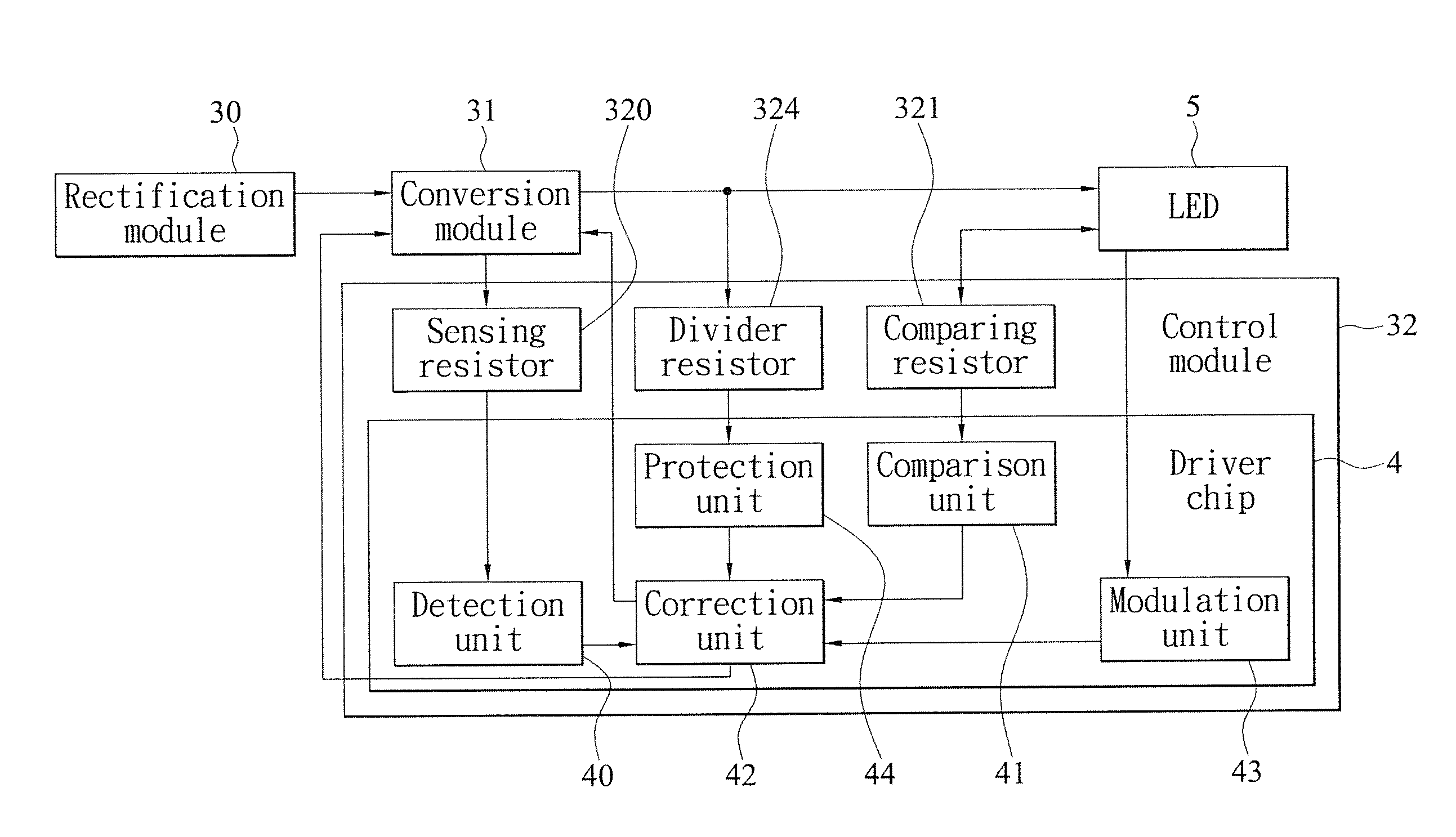
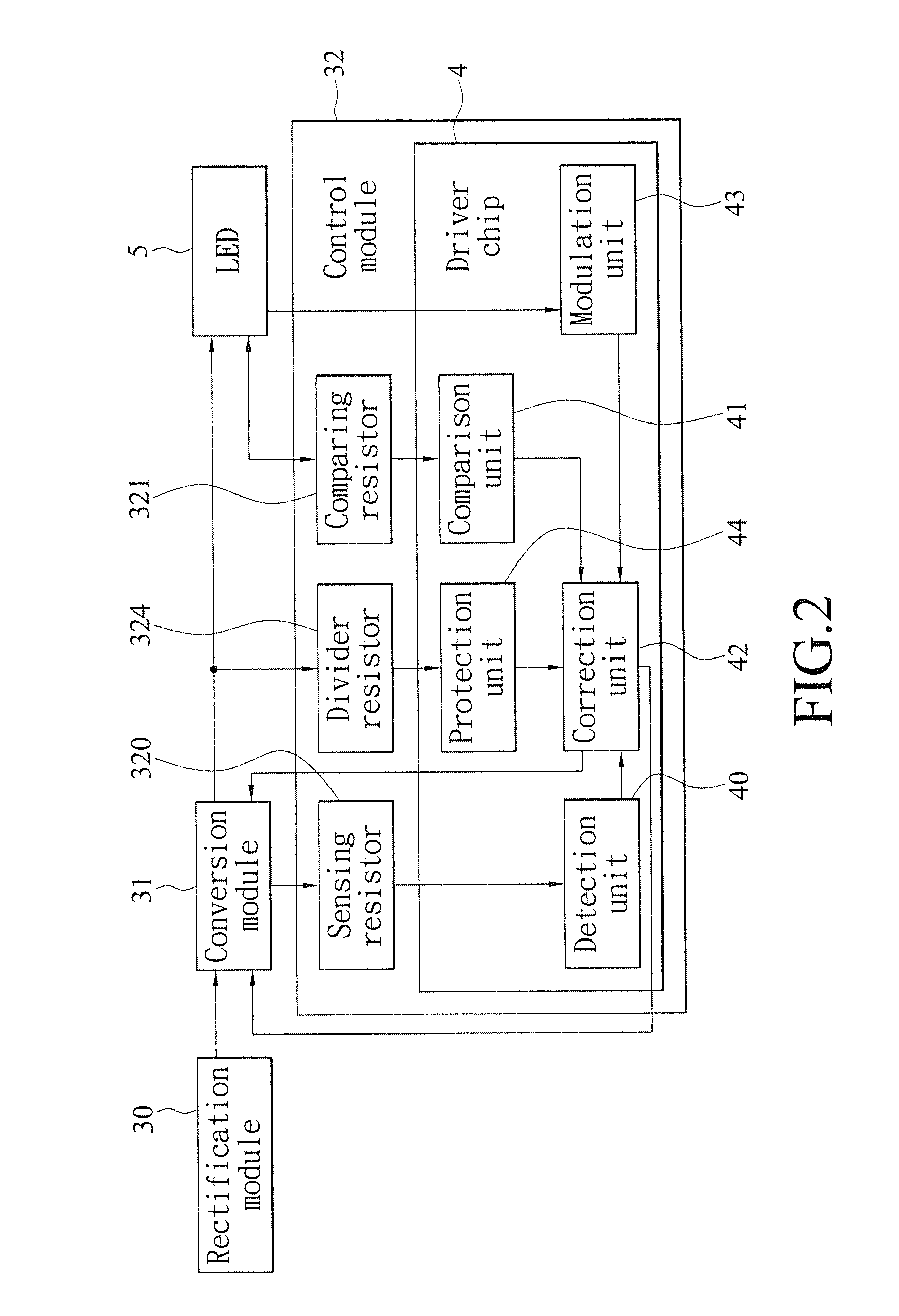
[0021]With reference to FIGS. 2 to 4 and 7 for a block diagram, a circuit diagram of a driver chip, a circuit diagram of the driver circuit and a waveform diagram of a preferred embodiment of the present invention respectively. As shown in the figures, a high-efficiency LED driver circuit 3 uses the high-efficiency LED driver chip 4 to detect its operating current IL and a driving current ILED of at least one LED 5 to correct the power factor and output a constant current, so as to achieve the effects of stabilizing the illumination brightness of the LED 5 and improving the circuit efficiency. The driver circuit 3 comprises a rectification module 30, a conversion module 31 and a control module 32. The control module 32 includes a sensing resistor 320, a comparing resistor 321, a sensing transistor 322, a ...


PUM


Abstract

Disclosed is a high-efficiency LED driver chip and a driver circuit of the chip, and the driver chip includes a detection unit, a comparison unit and a correction unit. The LED detection unit detects the operating current of the LED driver circuit by an external sensing resistor and an internal current mirror to output a setup signal, and the comparison unit detects the driving current of at least one LED by an external comparing resistor to output an initialization signal, so that the correction unit can output a correction signal according to the setup signal and the initialization signal to reduce the power loss of the circuit while maintaining the driving current constant, so as to improve the illumination quality and the service life of the LED.

Description

CROSS-REFERENCE TO RELATED APPLICATIONS[0001]This non-provisional application claims priority under 35 U.S.C. § 119(a) on Patent Application No(s). 101127973 filed in Taiwan, R.O.C. on Aug. 3, 2012, the entire contents of which are hereby incorporated by reference.BACKGROUND OF THE INVENTION[0002]1. Field of the Invention[0003]The present invention relates to the technical field of circuit devices for electric light sources, and more particularly to a low-cost high-efficiency LED driver chip and a driver circuit thereof capable of reducing the power loss of the overall circuit to achieve high electric power conversion efficiency effectively.[0004]2. Description of the Related Art[0005]At present, light emitting diode (LED) with its low power consumption, long life, small volume, quick response and low price hits the entire illumination market and becomes increasingly more popular in the application for illumination lamps such as desk lamps, patio lamps, signal lights, advertising bi...

Claims


Application Information

Patent Timeline
IPC IPC(8): H05B33/08H05B44/00
CPCH05B33/0848H05B45/38H05B45/3725H05B45/14
Inventor KUO, CHUN-CHIEHCHEN, KE-HORNGCHIU, SHAO-WEI
Owner ANWELL SEMICON CORP
Why Eureka
Try Eureka