Ink jet printing apparatus

a printing apparatus and jet technology, applied in printing, typewriters, other printing apparatuses, etc., can solve the problems of affecting the printing result, affecting the printing effect, and affecting the image quality, so as to achieve the effect of appropriate printing results

Active Publication Date: 2013-03-07
SEIKO EPSON CORP
View PDF2 Cites 26 Cited by
  • Summary
  • Abstract
  • Description
  • Claims
  • Application Information

AI Technical Summary

Benefits of technology

[0009]An advantage of some aspects of the invention is to provide an ink jet printing apparatus which can obtain a more appropriate printing result while avoiding contact between a swelling portion such as a seam and a printing head even if a printing target material having the swelling portion is used.
[0011]With the aspect of the invention, in the ink jet printing apparatus, the placement table on which the printing target material is placed includes the recess in which the swelling portion of the printing target material falls. Accordingly, the swelling portion of the printing target material is made to fall in the recess so as to reduce a risk that the swelling portion and the printing head make contact with each other. Further, the printing target material is supported on the placement table on a region excluding the recess so as to ensure flatness of a surface of the printing target material at the printing side. That is to say, fluctuation in a distance between the surface at the printing side and the printing head can be prevented or a degree of the fluctuation in the distance therebetween can be reduced, thereby obtaining a preferable printing result.
[0015]With the aspect of the invention, the strength of the suction through the suction hole can be adjusted. Therefore, the degree of falling of the swelling portion in the recess can be adjusted. With this, the distance between the swelling portion and the printing head can be set more appropriately.
[0017]With the aspect of the invention, the degree of the suction through the suction hole is made relatively strong in the case where the printing target material having relatively high rigidity is used in comparison with the case where the printing target material having low rigidity is used, in accordance with the rigidity of the printing target material. With this, even when the printing target material has high rigidity, the swelling portion can be made to fall in the recess reliably, thereby obtaining an appropriate printing result more reliably.
[0019]With the aspect of the invention, the degree of the suction through the suction hole is made relatively weak when ink is discharged at least onto the swelling portion in comparison with cases other than the ink discharging. With this, when ink is discharged onto the swelling portion, an adverse influence on ink landing accuracy due to suction can be prevented, or the adverse influence can be reduced.

Problems solved by technology

As a technical problem specific to the ink jet printing apparatus of this type, there arises a problem due to swelling of a surface of a printing target material (for example, woven fabric) on a printing side.
Therefore, there is a risk that a head surface of an ink jet printing head makes contact with the swelling portions at the time of printing and a printing result is adversely affected.
In contrast, if the ink jet printing head is made farther from the printing target material in order to solve the above-described problem, there arises a risk that image quality is lowered due to this distancing.
However, since the image recording portion is lifted with the mat board, fluctuation in a thickness of the mat board leads to fluctuation in a distance between the recording head and the needlework as it is.

Method used


Image

  • Ink jet printing apparatus
  • Ink jet printing apparatus
  • Ink jet printing apparatus

Examples


first embodiment

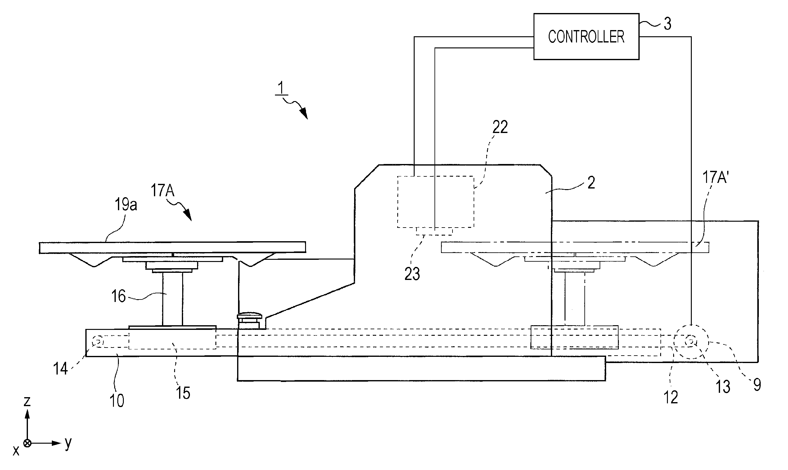
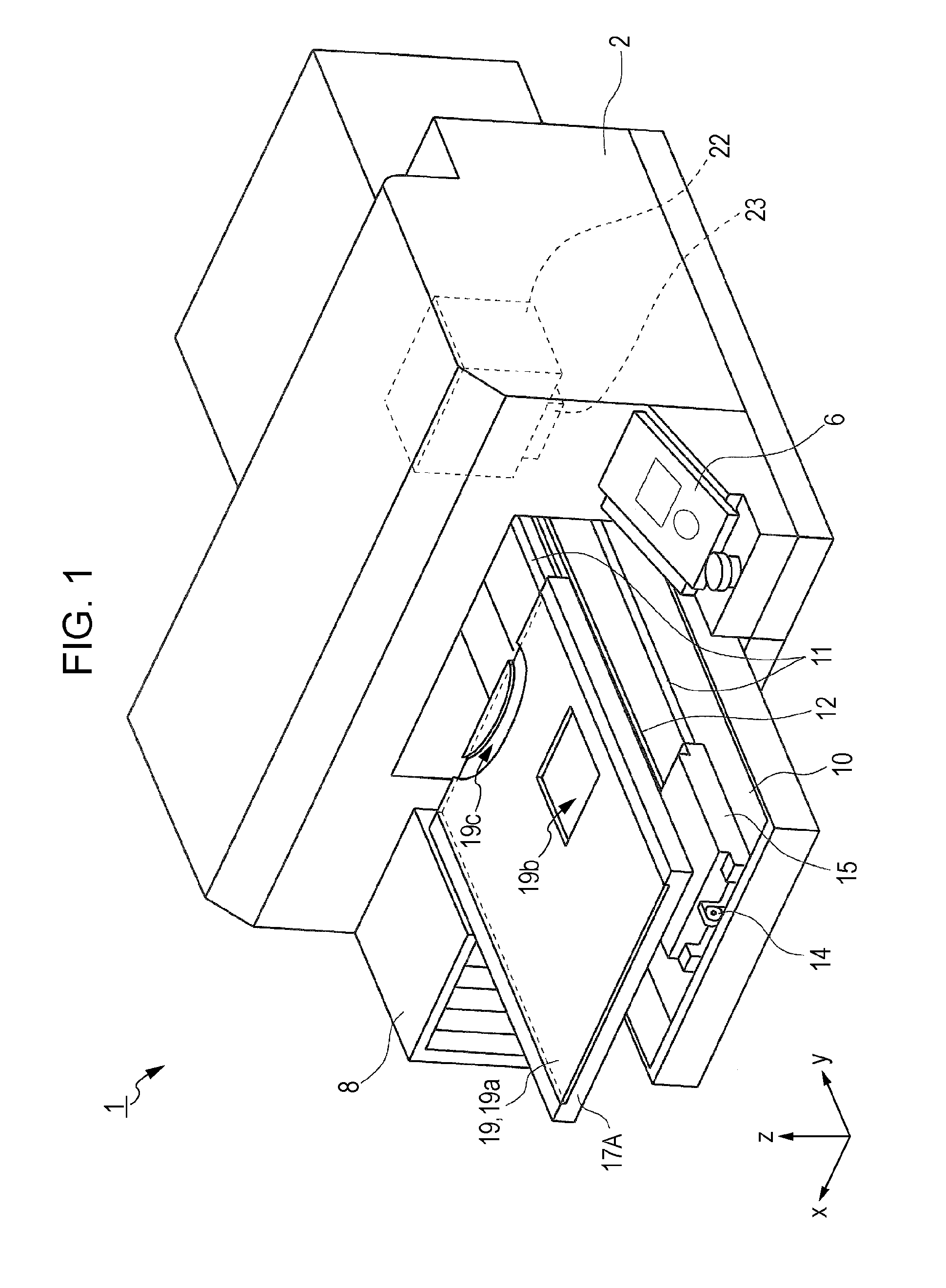
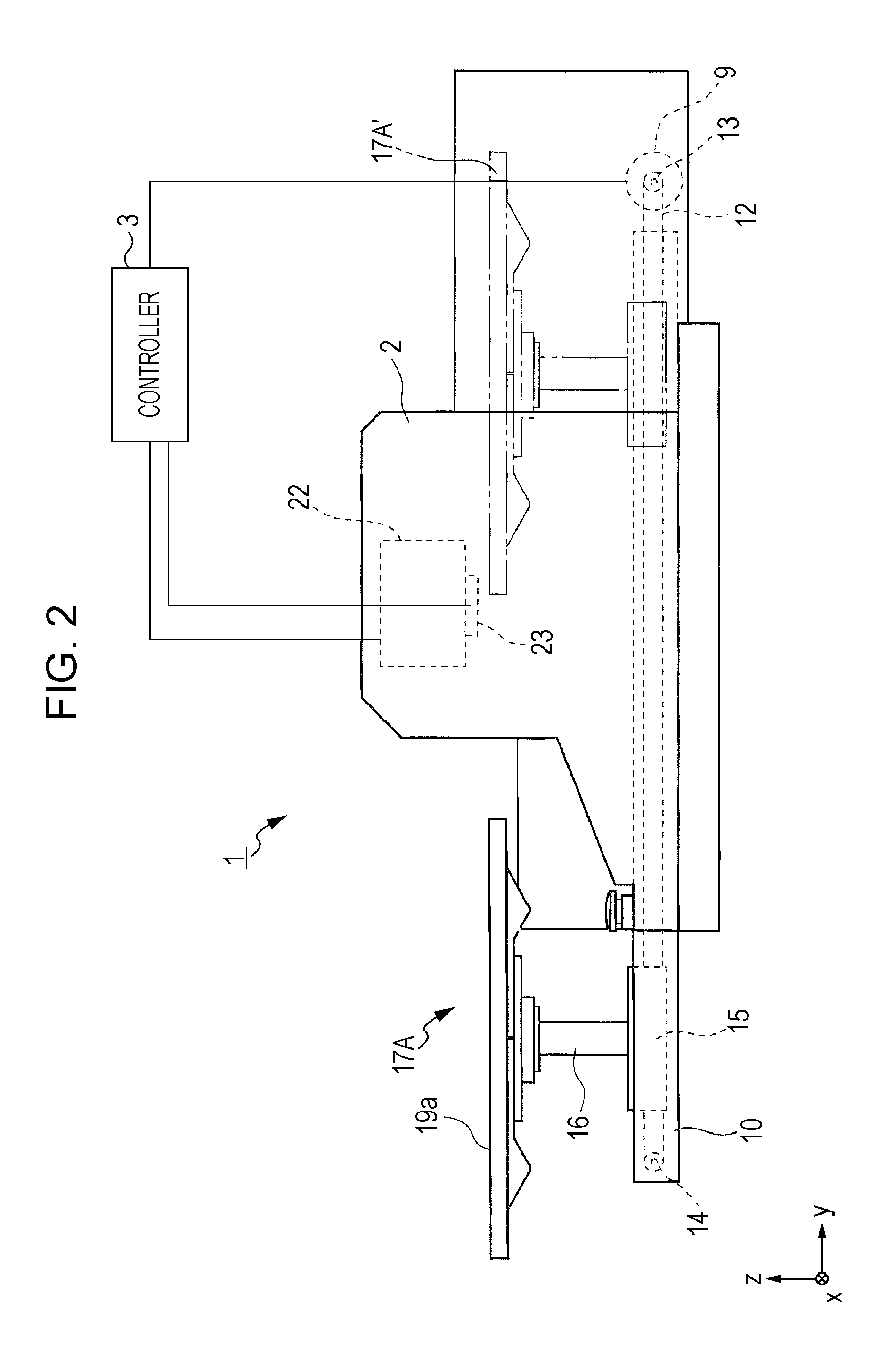
[0050]Subsequently, the placement table 17A according to the first embodiment of the invention is described in detail. As illustrated in FIG. 1 and FIG. 4, the placement table 17A includes recesses 19b and 19c in which swelling portions (in FIG. 3, M1 and M2) of the printing target material P fall.

[0051]To be more specific, as illustrated in FIG. 3, the T-shirt as an example of the printing target material P is formed such that a neck portion M1 and a breast pocket portion M2 (examples) are thick. Therefore, if the T-shirt is placed on a flat surface only, the neck portion M1 and the breast pocket portion M2 are made into a state of being swelled to the upper side with respect to a surface (upper surface of the printing target material P) at the printing side. This arises a risk that the neck portion M1 and the breast pocket portion M2 will rub with the ink jet head 23.

[0052]Accordingly, the recess 19c having a shape corresponding to the neck portion M1 is formed on the placement ta...

second embodiment

[0055]Next, the second embodiment of the invention will be described. On the placement table 17B included by the ink jet printing apparatus 1′ according to the second embodiment of the invention as illustrated in FIG. 5, suction holes for sucking the printing target material P are provided in recesses in which swelling portions of the printing target material P fall.

[0056]To be more specific, a hollow portion 17b is formed at the inner side of the placement table 17B as illustrated in FIG. 5. Further, a suction fan device 25 as a sucking unit arranged on the base 15 and the hollow portion 17b are connected to each other with a tube 26. A number of suction holes 18 (FIG. 6A) communicating with the hollow portion 17b are formed on the upper surface 17a of a main body of the placement table 17B. If the suction fan device 25 is operated, the printing target material P can be sucked through the suction holes 18. It is to be noted that strength of suction by the suction fan device 25 can ...

third embodiment

[0062]Next, the third embodiment of the invention will be described. The placement table 17C according to the third embodiment of the invention as illustrated in FIG. 8 is configured such that a depth of the recess 19c (or recess 19b) can be adjusted. Reference numerals 20A, 20B, and 20C indicate spacers having different thicknesses. The spacers 20A, 20B, and 20C are put in the recess 19c (or the recess 19b) so that the depth thereof can be made appropriate in accordance with a swelling degree of a swelling portion of the printing target material P.

[0063]Through-holes 20a are formed in the spacers indicated by the reference numerals 20B and 20C. On the other hand, no through-hole 20a is formed in the spacer indicated by the reference numeral 20A. In this manner, if the through-hole 20a is selected to be provided or not to be provided, it can be easily selected for the printing target material P to be sucked or not to be sucked through the suction holes 18. If the printing target mat...


PUM


Abstract

An ink jet printing apparatus includes a placement table on which recesses in which swelling portions of a printing target material fall are formed and the printing target material is placed, and an ink jet head that discharges ink onto a surface of the printing target material of a printing side placed on the placement table so as to execute desired printing. The swelling portions such as seams fall in the recesses on the printing target material so that the swelling portions and the ink jet head can be avoided from rubbing with each other.

Description

BACKGROUND[0001]1. Technical Field[0002]The present invention relates to an ink jet printing apparatus including a printing head which discharges ink onto a printing side of a surface of a printing target material to be transported so as to execute desired printing.[0003]2. Related Art[0004]In an apparel (clothing) manufacturer and a textile (fabric) manufacturer, existing “printing” in which a pattern and the like are printed on a surface of a fabric has been widely performed.[0005]Further, as a printing apparatus which performs printing, an ink jet printing apparatus which makes ink which has been discharged from a printing head adhere directly onto a printing target material so as to execute printing has been developed.[0006]As a technical problem specific to the ink jet printing apparatus of this type, there arises a problem due to swelling of a surface of a printing target material (for example, woven fabric) on a printing side. For example, swelling portions (raised portions) ...

Claims


Application Information

Patent Timeline
Patent Type & Authority Applications(United States)
IPC IPC(8): B41J2/01
CPCB41J3/4078B41J11/06B41J11/0085
Inventor MORIYA, YUKIYANAGISHITA, KENJI
Owner SEIKO EPSON CORP
Why Eureka
Try Eureka