Ink jet printing apparatus
a printing apparatus and jet technology, applied in printing, typewriters, other printing apparatuses, etc., can solve the problems of affecting the printing result, affecting the printing effect, and affecting the image quality, so as to achieve the effect of appropriate printing results
- Summary
- Abstract
- Description
- Claims
- Application Information
AI Technical Summary
Benefits of technology
Problems solved by technology
Method used
Image
Examples
first embodiment
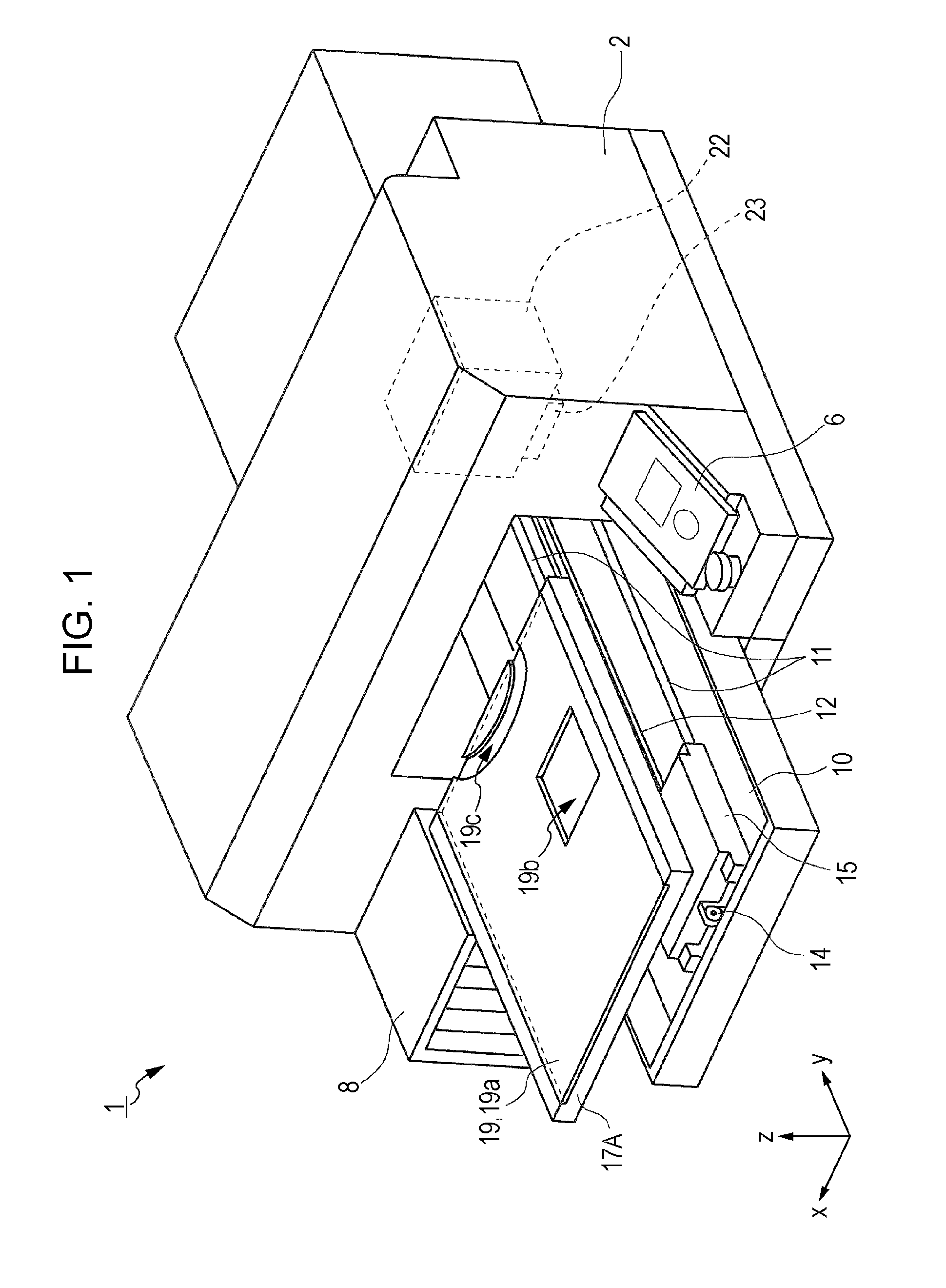
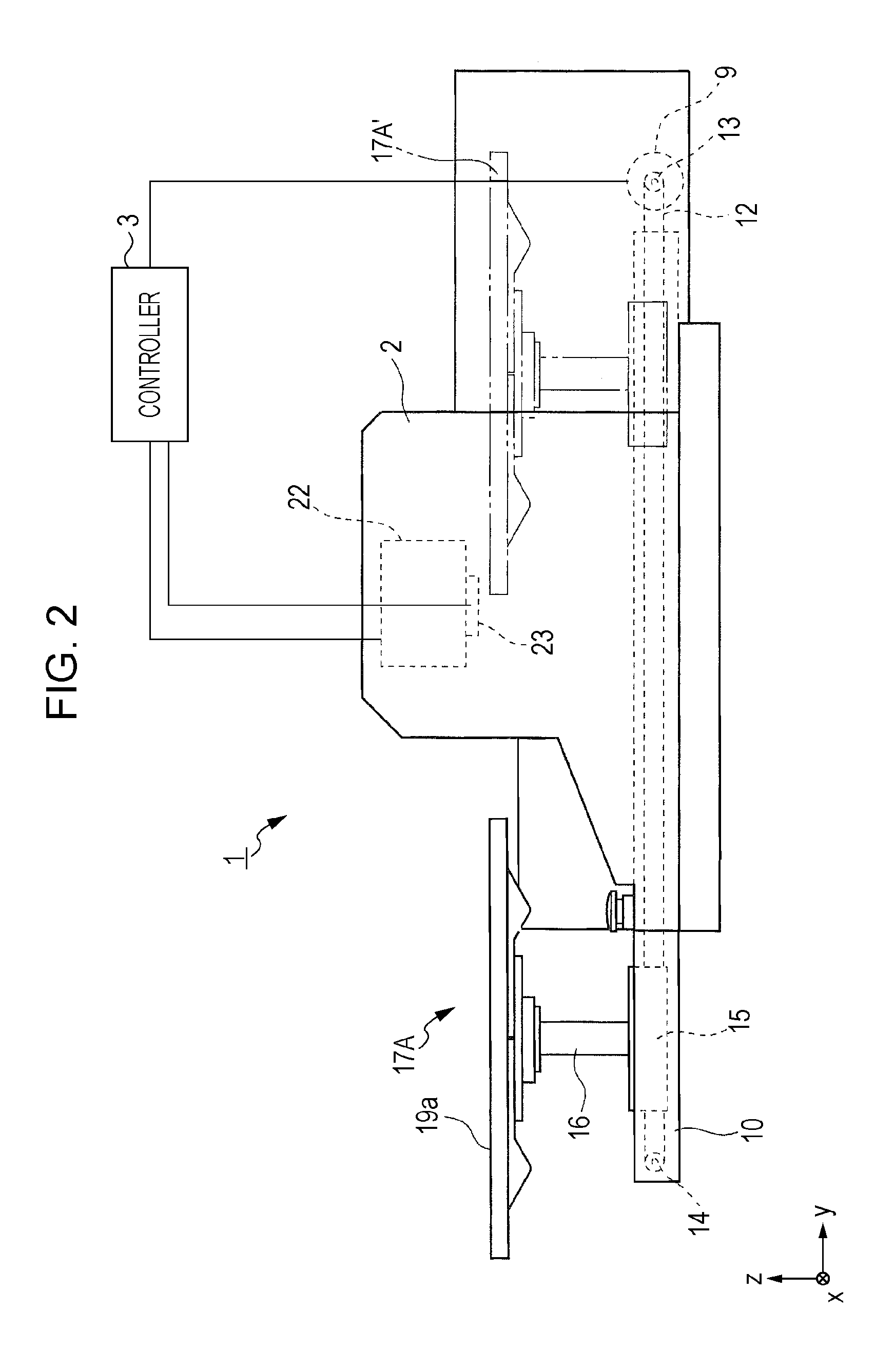
[0049]Subsequently, the placement table 17A according to the first embodiment of the invention is described in detail. As illustrated in FIG. 1 and FIG. 4, the placement table 17A includes recesses 19b and 19c in which swelling portions (in FIG. 3, M1 and M2) of the printing target material P fall.
[0050]To be more specific, as illustrated in FIG. 3, the T-shirt as an example of the printing target material P is formed such that a neck portion M1 and a breast pocket portion M2 (examples) are thick. Therefore, if the T-shirt is placed on a flat surface only, the neck portion M1 and the breast pocket portion M2 are made into a state of being swelled to the upper side with respect to a surface (upper surface of the printing target material P) at the printing side. This arises a risk that the neck portion M1 and the breast pocket portion M2 will rub with the ink jet head 23.
[0051]Accordingly, the recess 19c having a shape corresponding to the neck portion M1 is formed on the placement ta...
second embodiment
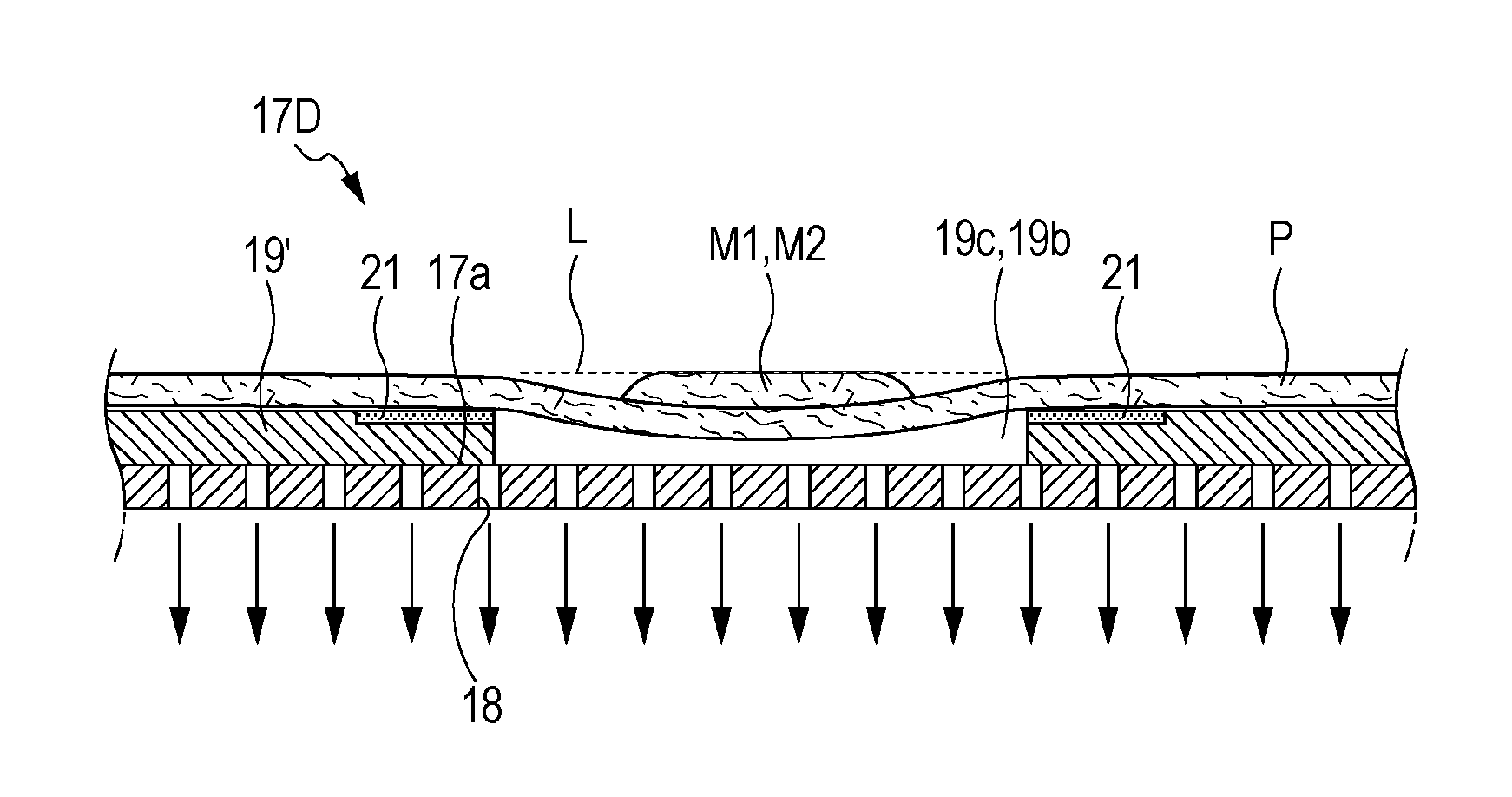
[0054]Next, the second embodiment of the invention will be described. On the placement table 17B included by the ink jet printing apparatus 1′ according to the second embodiment of the invention as illustrated in FIG. 5, suction holes for sucking the printing target material P are provided in recesses in which swelling portions of the printing target material P fall.
[0055]To be more specific, a hollow portion 17b is formed at the inner side of the placement table 17B as illustrated in FIG. 5. Further, a suction fan device 25 as a sucking unit arranged on the base 15 and the hollow portion 17b are connected to each other with a tube 26. A number of suction holes 18 (FIG. 6A) communicating with the hollow portion 17b are formed on the upper surface 17a of a main body of the placement table 17B. If the suction fan device 25 is operated, the printing target material P can be sucked through the suction holes 18. It is to be noted that strength of suction by the suction fan device 25 can ...
third embodiment
[0061]Next, the third embodiment of the invention will be described. The placement table 17C according to the third embodiment of the invention as illustrated in FIG. 8 is configured such that a depth of the recess 19c (or recess 19b) can be adjusted. Reference numerals 20A, 20B, and 20C indicate spacers having different thicknesses. The spacers 20A, 20B, and 20C are put in the recess 19c (or the recess 19b) so that the depth thereof can be made appropriate in accordance with a swelling degree of a swelling portion of the printing target material P.
[0062]Through-holes 20a are formed in the spacers indicated by the reference numerals 20B and 20C. On the other hand, no through-hole 20a is formed in the spacer indicated by the reference numeral 20A. In this manner, if the through-hole 20a is selected to be provided or not to be provided, it can be easily selected for the printing target material P to be sucked or not to be sucked through the suction holes 18. If the printing target mat...
PUM
 Abstract
Description
Claims
Application Information
 - R&D
- Intellectual Property
- Life Sciences
- Materials
- Tech Scout
- Unparalleled Data Quality
- Higher Quality Content
- 60% Fewer Hallucinations
Browse by: Latest US Patents, China's latest patents, Technical Efficacy Thesaurus, Application Domain, Technology Topic, Popular Technical Reports.
© 2025 PatSnap. All rights reserved.Legal|Privacy policy|Modern Slavery Act Transparency Statement|Sitemap|About US| Contact US: help@patsnap.com


