Shear-bonded molded bicycle component assembly

a bicycle and component technology, applied in the field of molded bicycle components, can solve the problems of limited commercial acceptance of molded bicycle wheel designs in general, high labor intensity of such traditional spoke designs, and limited structural integrity of molded bicycle wheel designs, so as to increase the bonding area and increase the structural integrity of the bond. , the effect of increasing the bonding area

Inactive Publication Date: 2000-10-31
DEMPSEY DOUGLAS E
View PDF71 Cites 28 Cited by
  • Summary
  • Abstract
  • Description
  • Claims
  • Application Information

AI Technical Summary

Benefits of technology

Accordingly, the present invention provides molded structural bicycle component designs, such as frame and wheel assembly designs, in which two or more portions can be molded and joined together in a manner which is both efficient from a manufacturing perspective and structurally sound under demanding applications. The designs may involve two halves which may be complementary, mirror images, or identical and which may be shear bonded together through the use of specifically designed flanges and recesses which allow the bonding to be perpendicular to the central plane. In some embodiments, this bonding is designed so as to increase the bonding area. This can increase the structural integrity of the bond for areas of particular stress. Further, the designs may incorporate halves which may act to achieve compression between the surfaces during the joining process. These designs can thus achieve a more structurally sound bond without any need for external assembly involvement. The designs may also include integral bearings, integral molded valve stem holes, and even valve stem access areas to avoid any need for drilling or other manufacturing steps.
It is one general goal of the invention to provide for a variety of molded bicycle component designs which can be efficiently manufactured. In keeping with this goal, one object is to allow for complementary halves to be molded and assembled. It is also an object to provide designs for which structural enhancements can be incorporated at varying locations. These structural enhancements may include additional internal ribs.
Another general goal of the invention is to provide bicycle component assembly designs which can withstand the stresses incident to demanding use. It is an object to provide for designs in which the strengths of the particular resultant bond can be adjusted throughout the component assembly and the weight / strength balance adjusted to suit the functional requirements of the application. Another object is, of course, to provide for an exceptionally strong bond between two molded halves of the bicycle component assembly. This object includes the creation of a shear bond which may be optimally configured to resist the stresses incidental to demanding uses.
Yet another general goal of the invention is to provide for methods and designs which minimize the amount of labor required in the assembly process. In keeping with this goal, one object is to allow for designs in which the two halves may be joined through bonding techniques without the need for additional fasteners (such as screws, bolt, and so forth) to minimize additional assembly steps. Similarly, an object is to allow for bicycle component assembly designs, which include a hole for a valve stem or the like for a wheel and yet which do not require a separate drilling step. Yet another object in keeping with this general goal is to allow for techniques through which molded designs may be bonded together in an automated fashion. One example of this includes the object of utilizing electromagnetic bonding technology. In keeping with the general goal of minimizing assembly labor, the invention also has as an object allowing for integral components such as bearings or spacers. This may also include the incorporation of integral cosmetics and colorants and the like so that once joined, the assembly is substantially complete.
Yet another general goal of the invention is to provide for a design which can be adapted based upon the particular requirements of the many varying applications which are possible. In keeping with this goal, an object is to allow for both the increase or decrease in bonding area throughout various portions of the molded bicycle components. This allows for more efficient designs and assembly. Yet another object in keeping with this general goal is to provide for designs which can adapt and utilize polyurethane and other materials in a most efficient manner.

Problems solved by technology

The labor intense nature of such traditional spoke designs is one aspect which has great impact upon the cost of bicycle wheels.
In spite of the rather obvious advantage of applying molding technology to this field, the technical challenges incidental to producing a molded wheel design have greatly limited the commercial acceptance of molded bicycle wheel designs in general.
One of these challenges is the need to maintain light weight and yet strong structure.
This can limit the design characteristics.
By analogy to I-beam construction, it can be more efficient to move structure off the axis, but this does not lend itself to the most simple molding processes.
On the other hand, molding is more challenging for hollow items.
Surprisingly, these and other technological hurdles have caused structural challenges for the field of bicycle wheels as its applications are actually one of the more demanding.
Perhaps paradoxically, the challenges of applying molding technology have even lead toward increased expense for some designs.
Structurally, molded wheel designs have been faced with the challenge of allowing for two-part designs which can be joined together in a fashion that can withstand the significant stresses of such applications.
While such a technique for joining the halves might work in low-stress applications such as the children's design as shown in that patent, singular fastening devices such as the barbs have an undesirable incident of concentrating stresses when the wheel is in use.
Since the materials frequently used in molding items are not preferably materials which are particularly strong, this concentration of stresses has to some extent limited applications to items such as children's vehicles and the like.
While for some designs such a technique might actually achieve sufficient structural integrity, obviously the assembly required for such designs degrades the efficiency which is a supposed hallmark of molded wheel designs in the first place.
Although such a design does overcome the challenge of properly joining two or more parts together, it fails to achieve the most important goal of manufacturing efficiency.
In fact the process is so expensive that the end wheel is significantly more expensive than traditional, albeit inefficient, spoke designs.
Obviously, this direction does not achieve the low cost manufacturing efficiencies which are considered to be the hallmark of many molded wheel designs.
First, the attempts by those skilled in the art were directed away from designing the bond and wheel in a manner which was structurally appropriate.
In some regards, they simply seemed to accept that bonding alone would not represent an adequate approach and may have even failed to understand that the problem lay in properly designing the wheel, not in applying different technologies.

Method used


Image

  • Shear-bonded molded bicycle component assembly
  • Shear-bonded molded bicycle component assembly
  • Shear-bonded molded bicycle component assembly

Examples


Embodiment Construction

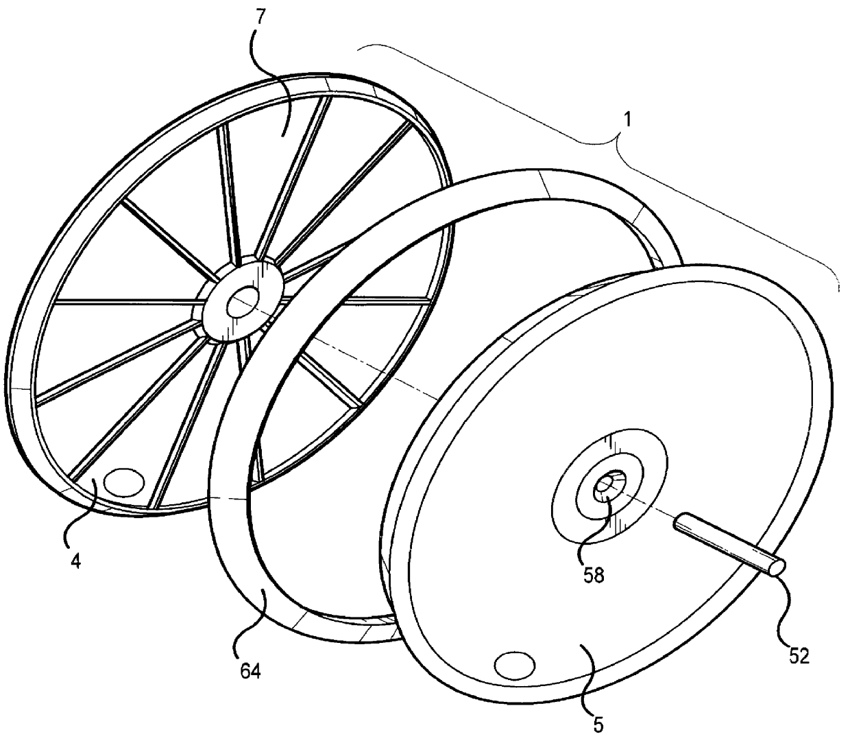
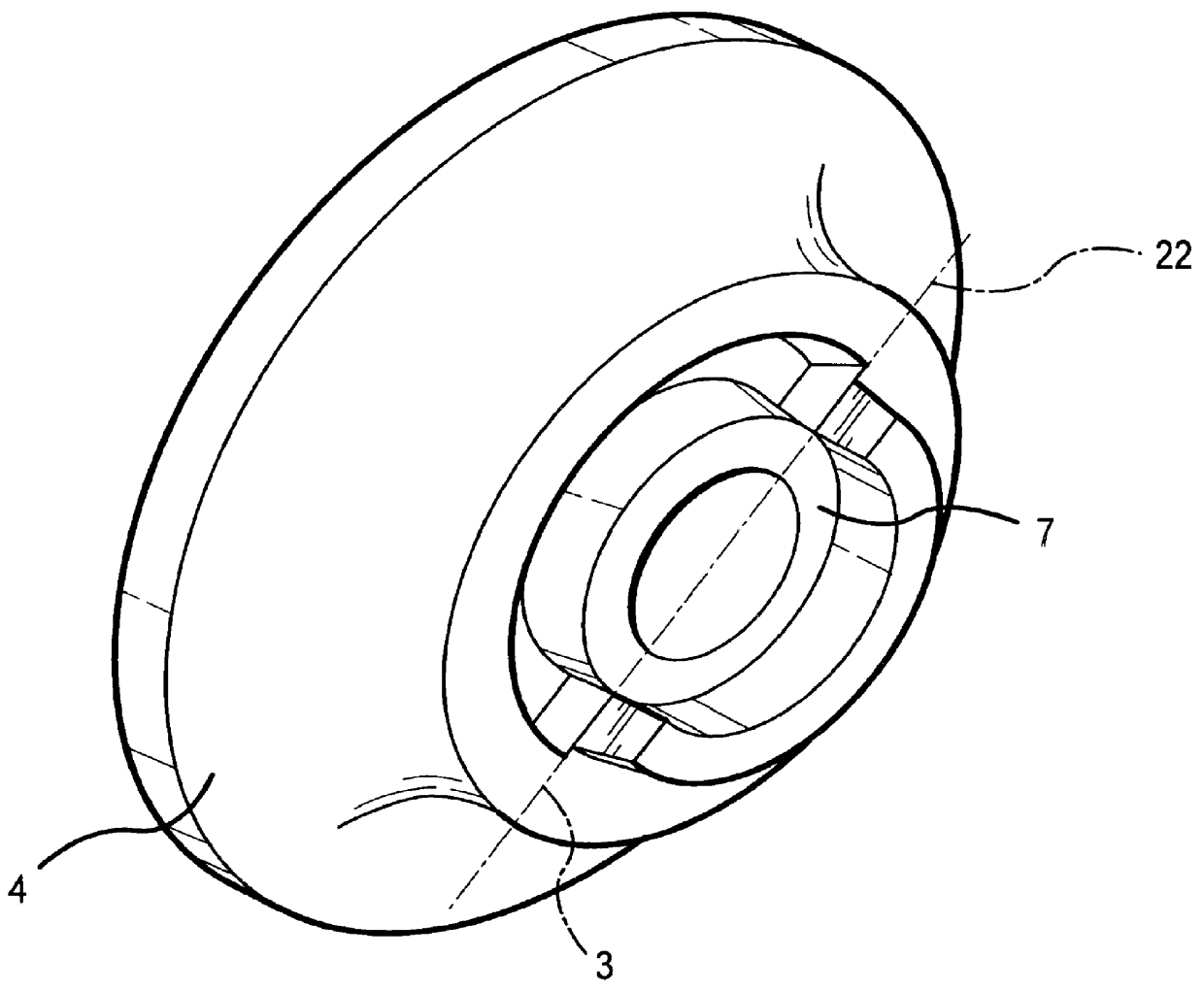
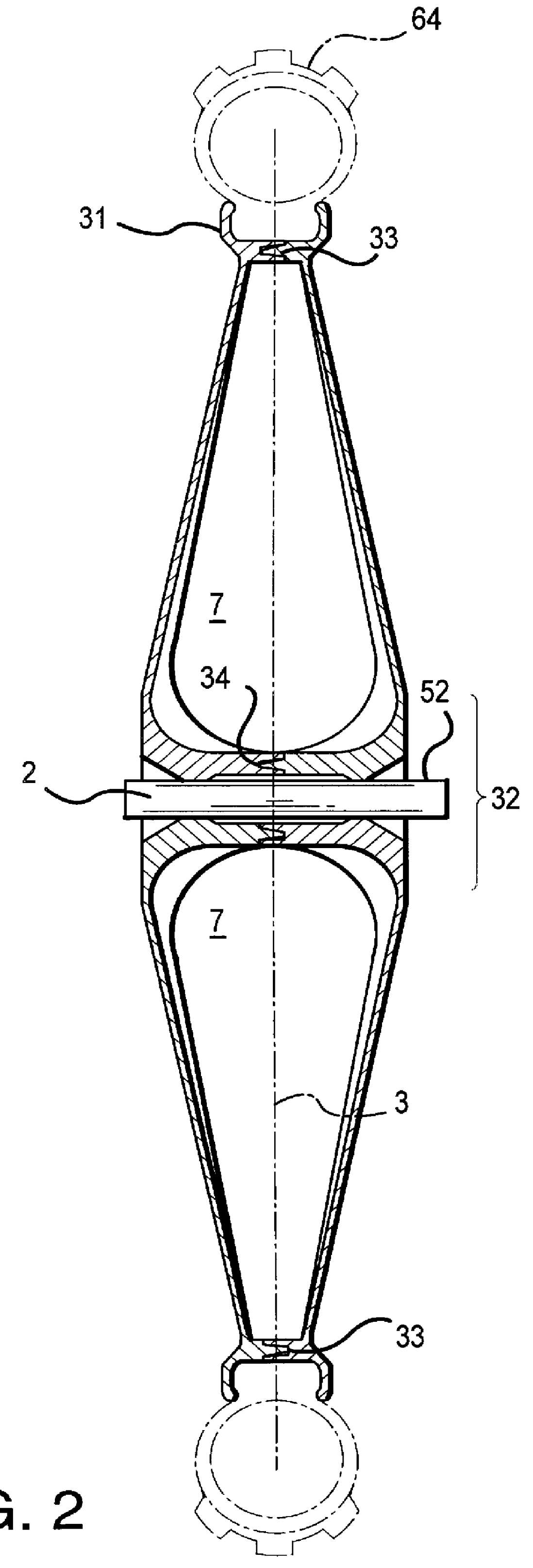
As mentioned earlier, the present invention includes a variety of components that may be used in different combinations, depending on the application that needs to be addressed. The invention is designed primarily to take advantage of a molded system and method for bicycle structural components of a particular and novel design and combine and modify them as needed for a variety of shapes, sizes, and orientations, as will be explained in more detail as the figures are described. This invention is intended to encompass a wide variety of uses in this specialized field. Elements, functions, and procedures that distinguish the present invention will be noted where appropriate.

As can be easily understood, the basic concepts of the present invention may be embodied in a variety of ways. It involves both methods and devices to accomplish the appropriate method. In this patent, the methods are disclosed as part of the results shown to be achieved by the various devices described and as steps...


PUM

PropertyMeasurementUnit
angleaaaaaaaaaa
thicknessaaaaaaaaaa
distanceaaaaaaaaaa

Abstract

A molded structural bicycle component design, such as wheels and frames, which may incorporate complementary halves and at least one shear bond to allow efficient manufacturing and assembly. The molded design which may be applied in a host of different applications, including a bicycle frame and wheel, where demanding loads exist in normal use. Details of the joint and its design are provided. Integral bearings, foam tire adaptations, symmetrically opposite designs, and compression bonding techniques are described. Various cross sections may be made at different stress areas. A method of inserting a reinforcing tube in various high stress areas is also described. A host of bonding techniques including the use of electromagnetically active material are accommodated by the designs. The design may include the use of spacers in the vicinity where methods of retention of accessories or components require compressing from both sides such as the wheels, head tube, bottom bracket, and suspension attachment. The invention may include semicircular boundaries of a wheel assembly so as to define a valve stem hole after assembly.

Description

I. BACKGROUND OF THE INVENTIONThis invention relates generally to molded bicycle components, including wheel designs, frames, and the like which join two halves together in order to form a single assembly. Specifically, the invention focuses upon bicycle component assembles which are efficient to manufacture and assemble, and yet which also have structural integrity similar to that of traditional bicycle components such as bicycle frames, handle bar designs, and wheel designs (including spoke designs) which are molded from multiple pieces and bonded into one assembly.Regarding the wheel aspect, obviously, the wheel has been around for some time; it may even be considered the most fundamental invention of mankind. In spite of this history, the wheel is still the subject of continued improvement. These improvements are not merely efforts to "reinvent the wheel", they are actually incremental improvements which specifically adapt the wheel to different applications and make it more eff...

Claims


Application Information

Patent Timeline
Patent Type & Authority Patents(United States)
IPC IPC(8): B29C65/02B29C65/36B29C65/56B29C65/58B29C65/34B60B5/02B60B5/00B29C65/06B29C65/08B29C65/48
CPCB29C65/02B29C66/54B60B5/02B29C65/3644B29C65/58B29C65/0672B29C65/08B29C65/48B29C65/4895B29C66/547B29L2015/006B29L2031/322B29C66/8322B29C66/63B29C66/1248B29C66/55
Inventor DEMPSEY, DOUGLAS E.
Owner DEMPSEY DOUGLAS E
Why Eureka
Try Eureka