Glass Cutting Apparatus With Bending Member and Method Using Thereof

a glass cutting and bending technology, applied in glass making apparatus, manufacturing tools, transportation and packaging, etc., can solve the problems of inconvenient cutting of glass sheets, and inability to cut large or thick glass sheets, etc., to achieve easy cutting, control the degree of bending of glass sheets, and facilitate the cutting process

Inactive Publication Date: 2009-02-26
K ENG
View PDF2 Cites 26 Cited by
  • Summary
  • Abstract
  • Description
  • Claims
  • Application Information

AI Technical Summary

Benefits of technology

[0010]In the glass cutting apparatus having a bending unit and the method of cutting glass using the same according to the present invention, there are the following advantages.
[0011]First, because the bending unit is provided such that the upper end thereof is disposed higher than the upper surface of a stage unit, a medial portion of a glass sheet is lifted while opposite ends thereof sag. Thus, stress is concentrated on the medial portion of the glass sheet to be cut. Hence, the glass sheet can be easily cut even using relatively little energy.
[0012]Particularly, the bending unit is disposed behind a laser generating unit, so that the bending unit pushes a cut part of the glass sheet upwards, thus making it easy to conduct the cutting process.
[0013]Second, the degree of bending of the glass sheet can be controlled by adjusting the height of the bending unit. Therefore, depending on the thickness and size of the glass sheet, the intensity of stress applied to a desired part of the glass sheet to be cut can be adjusted.
[0014]Third, a plurality of air suction holes is formed in the stage unit, so that the glass sheet is prevented from undesirably sliding, and the air suction holes along with the bending unit can further bend the medial portion of the glass sheet, that is, the part to be cut. Therefore, stress is further concentrated on the desired part of the glass sheet, thus the glass sheet can be cut using relatively little energy more easily.
[0015]Fourth, the bending unit is coupled to the laser generating unit by a support unit, so that, despite having a simple structure, the bending unit can be constructed to integrally move with the laser generating unit.

Problems solved by technology

However, the conventional cutting method has problems in that cut ends of a glass sheet are inferior and in that it is not suitable for cutting large or thick glass sheets.
However, for a glass sheet which is large and thus heavy, friction is high.
Such friction acts as stress interfering with cutting.
Thus, a cutting process is not easily conducted, and, even if the cutting process is completed, the quality of cut ends of the glass sheet is low.

Method used


Image

  • Glass Cutting Apparatus With Bending Member and Method Using Thereof
  • Glass Cutting Apparatus With Bending Member and Method Using Thereof
  • Glass Cutting Apparatus With Bending Member and Method Using Thereof

Examples


first embodiment

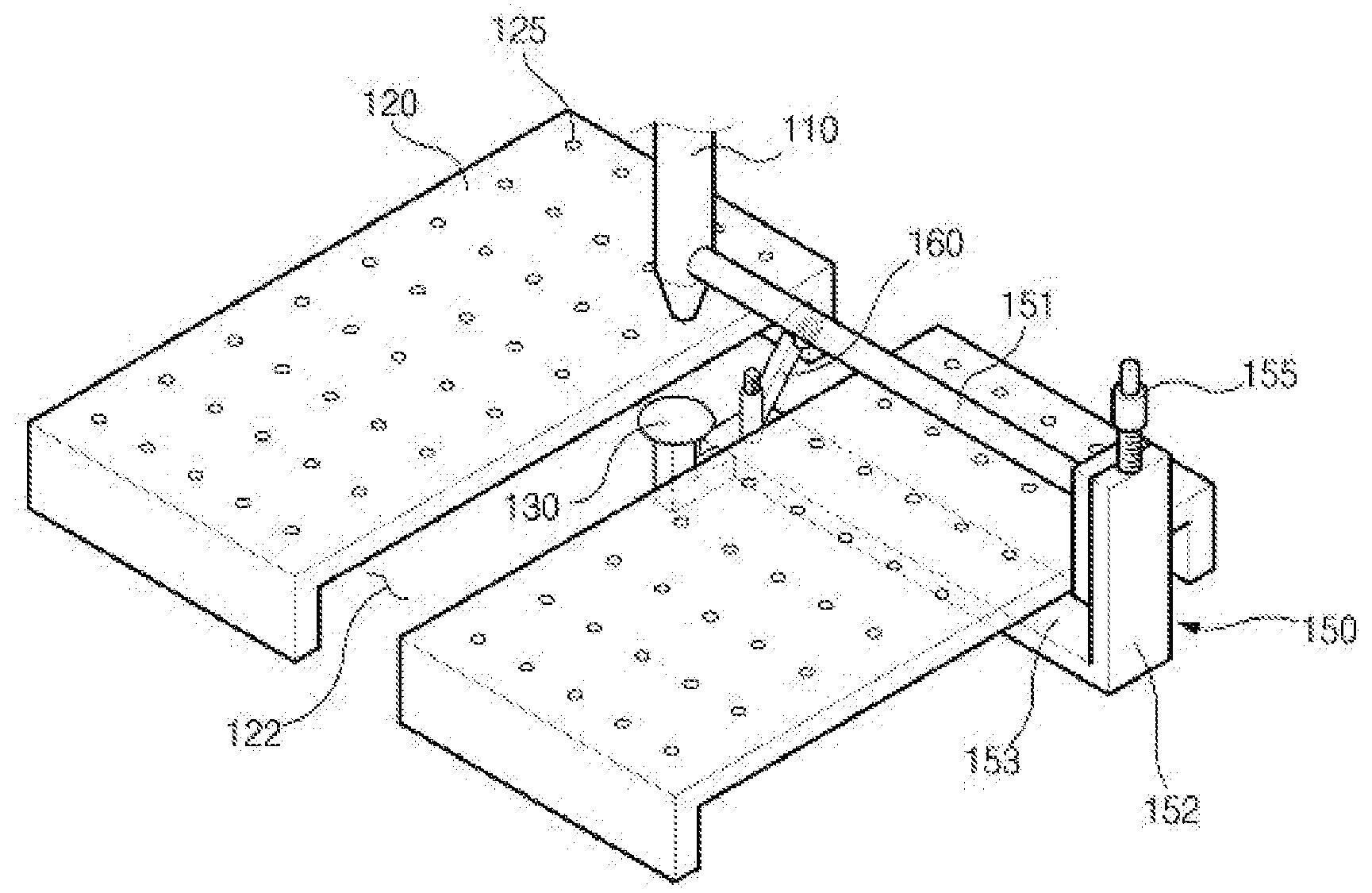
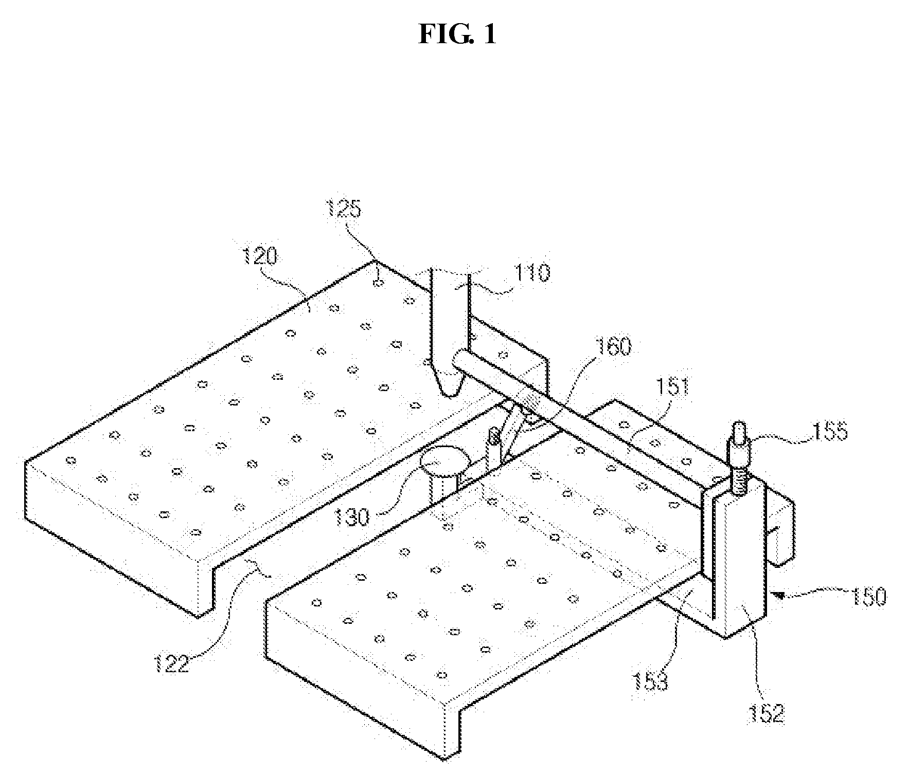
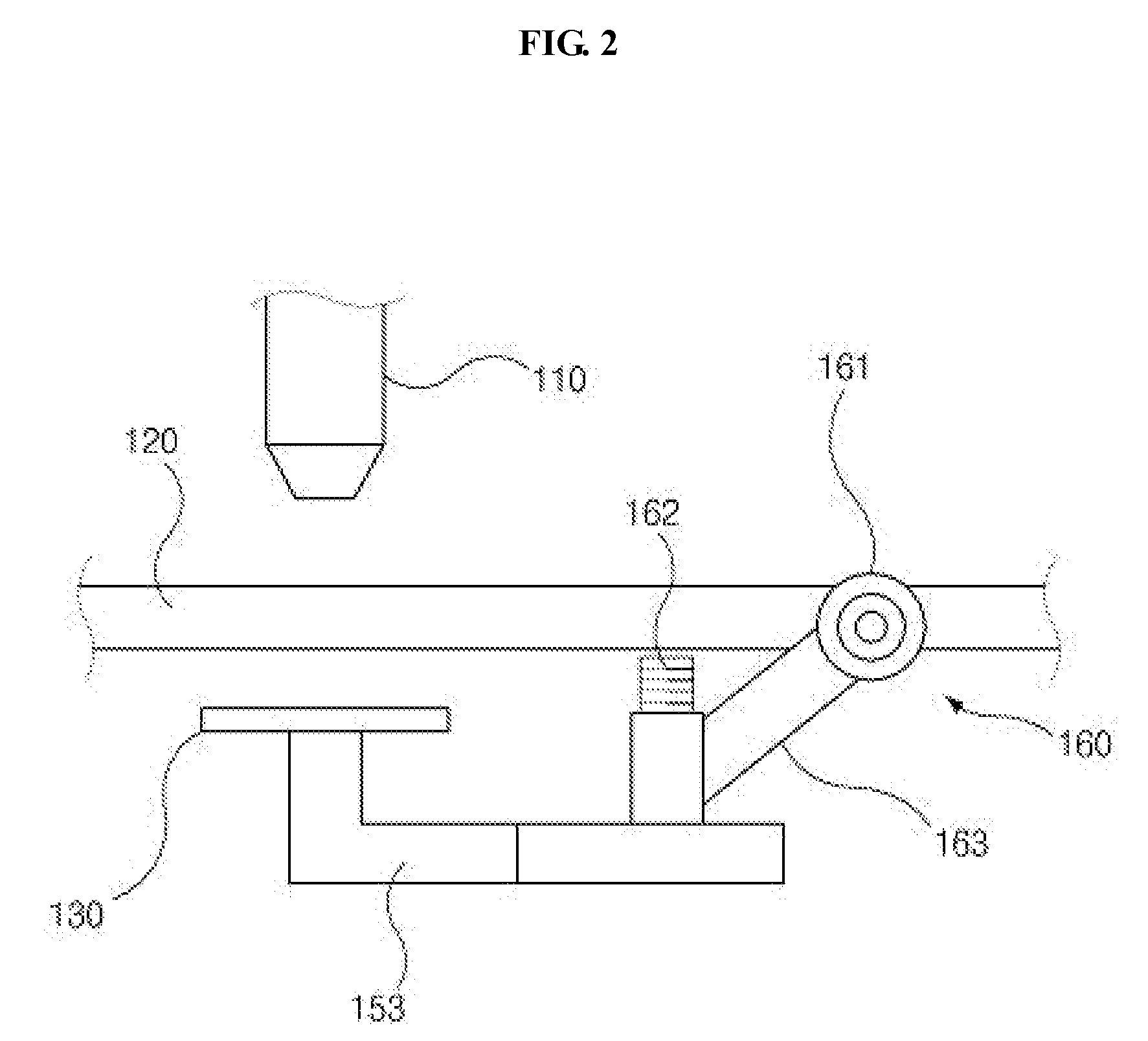
[0045]As shown in FIGS. 1 through 3, the first embodiment includes a laser generating unit 110, a stage unit 120, a lower reflecting plate 130, a support unit 150 and a bending unit 160.

[0046]The laser generating unit 110 generates a laser beam and radiates it onto a glass sheet 140, in the same manner as a conventional laser generating unit 110. The laser generating unit 110 moves forwards and backwards.

[0047]The stage unit 120 is provided below the laser generating unit 110 and supports the glass sheet 140 thereon. A guide path 122, along which the lower reflecting plate 130 and the bending unit 160 are moved, is formed at a medial position through the stage unit 120.

[0048]The guide path 122 may be a groove, which is formed by concavely machining the upper surface of the stage unit 120, or, alternatively, may be a gap defined between two separated bodies of the stage unit 120, as shown in FIGS. 1 and 3.

[0049]The lower reflecting plate 130 is disposed directly below the laser gener...

second embodiment

[0076]As shown in FIGS. 4 and 5, the second embodiment includes a laser generating unit 210, a stage unit 220, a lower reflecting plate 230, a support unit 250 and a bending unit 260.

[0077]The constructions of the laser generating unit 210, the stage unit 220, which is provided with a guide path 222 and air suction holes 225, the lower reflecting plate 230 and the bending unit 260 are the same as those of the first embodiment, therefore further explanation will be omitted, and the support member 250 will be mainly explained.

[0078]As shown in FIGS. 5 and 6, the support member 250 is provided behind the laser generating unit 210 and is coupled to the lower reflecting plate 230 and the bending unit 260.

[0079]Therefore, the lower reflecting plate 230 and the bending unit 260 are integrated with the laser generating unit 210 through the support unit 250, thus the lower reflecting plate 230 moves along with the laser generating unit 210.

[0080]The support unit 250 includes an upper horizon...

third embodiment

[0086]FIG. 6 is a perspective view of a glass cutting apparatus, according to the present invention.

[0087]As shown in FIG. 6, the third embodiment includes a laser generating unit 310, a stage unit 320, a lower reflecting plate 330, a moving means, a bending unit 360 and a control unit (not shown).

[0088]The constructions of the laser generating unit 310, the stage unit 320, which is provided with a guide path 322 and air suction holes 325, the lower reflecting plate 330 and the bending unit 360 are the same as those of the first embodiment, therefore further explanation will be omitted, and the moving means and the control unit will be mainly explained.

[0089]The moving means includes a first carrying unit 350, which moves the laser generating unit 310 forwards and backwards, and a second carrying unit 360, which moves the lower reflecting plate 330 and / or the bending unit 360 forwards and backwards.

[0090]The first carrying unit 350 includes a horizontal support bar 351, which is cou...


PUM

PropertyMeasurementUnit
speedaaaaaaaaaa
widthaaaaaaaaaa
widthaaaaaaaaaa

Abstract

Disclosed herein is glass cutting apparatuses and methods of cutting glass using the glass cutting apparatuses. More particularly, disclosed is a glass cutting apparatus which cuts a glass sheet (140) by forming a crack in the glass sheet using a laser beam and by lifting the glass sheet using a bending unit (160), and a method of cutting glass using the glass cutting apparatus.

Description

TECHNICAL FIELD[0001]The present invention relates, in general, to a glass cutting apparatus and a method of cutting glass using the glass cutting apparatus and, more particularly, to a glass cutting apparatus which cuts a glass sheet by forming a crack in the glass sheet using a laser beam and lifting the glass sheet using a bending unit, and a method of cutting glass using the glass cutting apparatus.BACKGROUND ART[0002]In conventional arts, to cut glass sheets, blades provided with diamonds at ends thereof have been used.[0003]However, the conventional cutting method has problems in that cut ends of a glass sheet are inferior and in that it is not suitable for cutting large or thick glass sheets.[0004]To solve the above problems, recently, a method of cutting a glass sheet using a laser beam has been used. In this method, a glass sheet is placed on a stage unit and, thereafter, a laser beam is radiated onto the glass sheet, thus cutting the glass sheet.[0005]In this case, the gla...

Claims


Application Information

Patent Timeline
Patent Type & Authority Applications(United States)
IPC IPC(8): B26F3/00
CPCB23K26/4075B26F3/002C03B33/091C03B33/033B65G2249/04B23K26/40B23K2103/50Y10T225/12Y10T225/325
Inventor NA, YOUN-HOJUNG, BYUNG-JINWOO, JUN-YOUNGPARK, MU-KYUNKIM, JUNG HYUN
Owner K ENG
Why Eureka
Try Eureka