Frequency-variable lc filter and high-frequency front end circuit

a filter and frequency variable technology, applied in filters, multiple-port networks, electrical equipment, etc., can solve the problems of increasing circuit size and and achieve the effect of reducing the steepness of attenuation characteristics, reducing the size of simple configuration, and reducing the loss of bandpass characteristics

Active Publication Date: 2018-07-12
MURATA MFG CO LTD
View PDF0 Cites 18 Cited by
  • Summary
  • Abstract
  • Description
  • Claims
  • Application Information

AI Technical Summary

Benefits of technology

[0040]The present disclosure can provide a frequency-variable LC filter capable of decreasing loss of bandpass characteristics and decreasing a difference between steepness of attenuatio

Problems solved by technology

However, the frequency-variable LC filter disclosed in Patent Document 1 uses four variable capacitors to adjust the characteristics, resulting in increase in a circuit size.
Furthermore, the frequency-variable LC filter disclosed in Patent Document 1 has the configurati

Method used


Image

  • Frequency-variable lc filter and high-frequency front end circuit
  • Frequency-variable lc filter and high-frequency front end circuit
  • Frequency-variable lc filter and high-frequency front end circuit

Examples


first embodiment

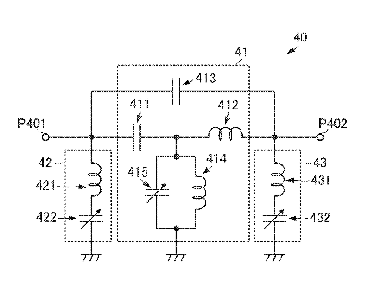
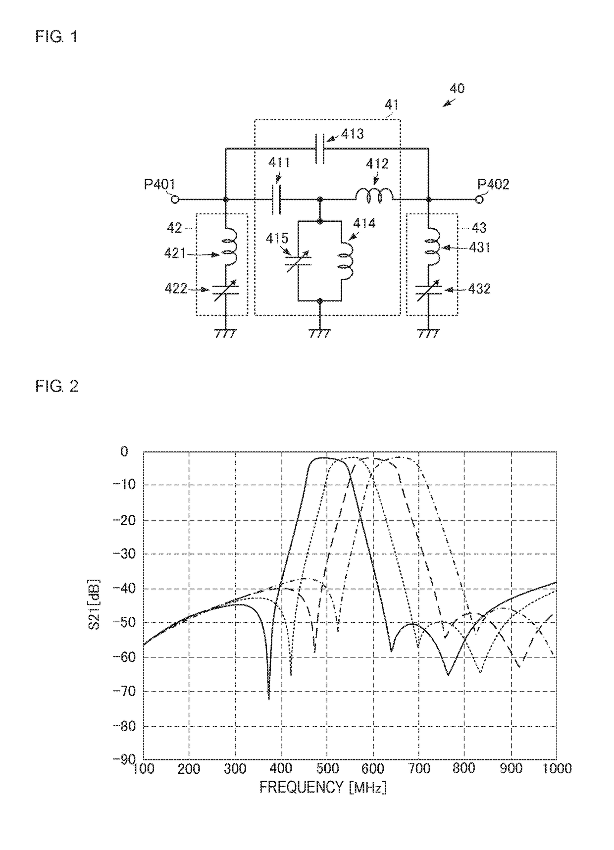
[0085]FIG. 2 is a graph illustrating bandpass characteristics of the frequency-variable LC filter in the present disclosure. As illustrated in FIG. 2, usage of the frequency-variable LC filter 40 can form the attenuation poles at both sides of the pass band with a pass band width of approximately 100 [MHz]. Furthermore, the attenuation can be made difficult to be decreased in frequency bands at the opposite sides to the pass band with respect to the respective attenuation poles and desired attenuation can be realized in a wide frequency band. In addition, the attenuation can be increased at both of the high frequency side and the low frequency side of the pass band and the frequency band in which the desired attenuation is provided can be enlarged.

[0086]In particular, as illustrated in FIG. 1, the inductor 412 of the first series arm LC filter circuit 41 is directly connected to the second connection terminal P402 without necessarily the capacitor interposed therebetween, thereby ma...

second embodiment

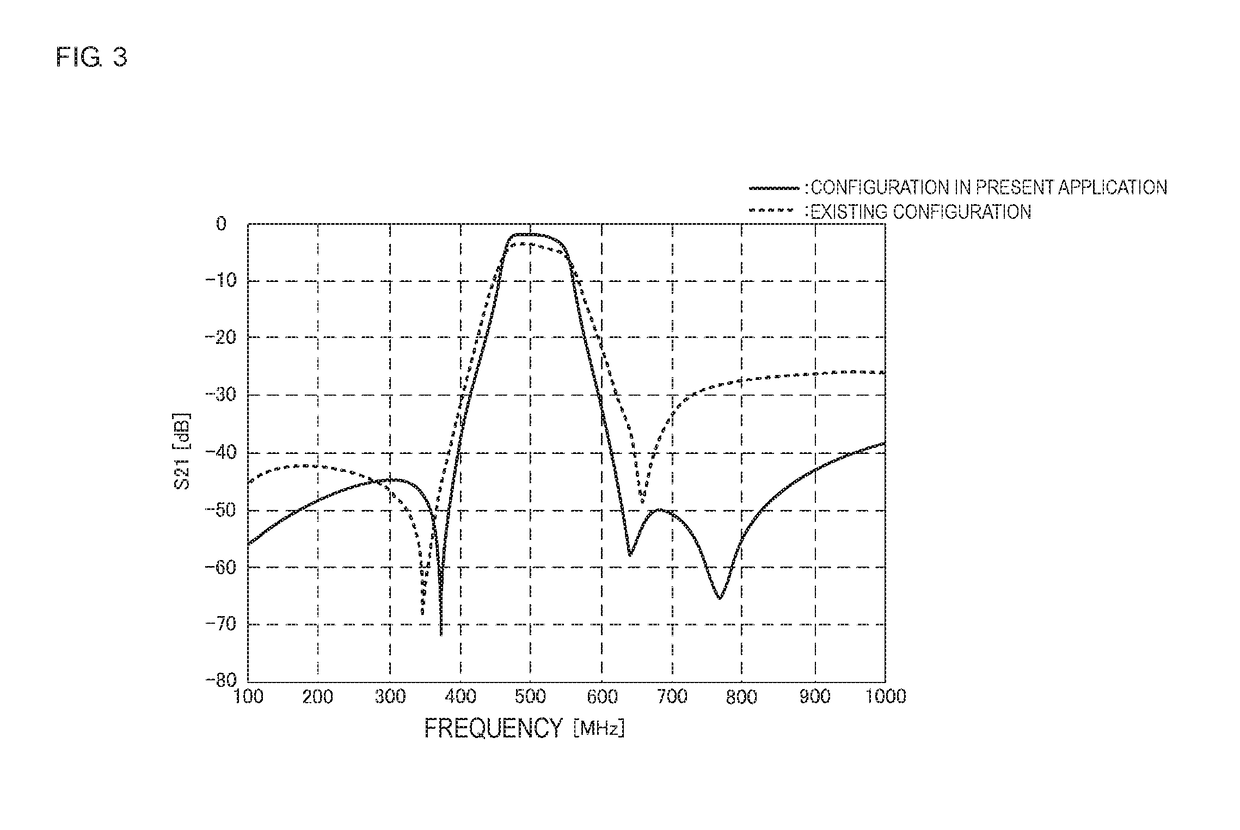
[0099]The bandpass characteristics as illustrated in FIG. 5 are provided by causing the inductor 412 that is directly connected to the second connection terminal P402 to be magnetically coupled with another inductor as described above. FIG. 5 is a graph illustrating the bandpass characteristics of the frequency-variable LC filter in the present disclosure. As illustrated in FIG. 5, usage of the configuration of the frequency-variable LC filter 40A, 40B, or 40C can make the attenuation characteristics steeper while maintaining low loss in the pass band in comparison with a mode that is not magnetically coupled.

[0100]The inductor 412 is caused to be magnetically coupled with another inductor in the embodiment. However, inductors that are caused to be magnetically coupled with each other among the inductor in the first parallel arm LC filter circuit, the inductor in the LC series circuit, the inductor in the LC parallel circuit, and the inductor in the second parallel arm LC filter cir...

fourth embodiment

[0137]Next, FIG. 11A is a circuit diagram of a frequency-variable LC filter 40F according to the present disclosure.

[0138]The frequency-variable LC filter 40F is different from the frequency-variable LC filter 40 in the first embodiment in a point that it includes a first parallel arm LC filter circuit 42F in order to further improve the steepness of the attenuation characteristics. The first parallel arm LC filter circuit 42F is configured by adding a fixed capacitor 423 to the first parallel arm LC filter circuit 42.

[0139]As illustrated in FIG. 11A, the fixed capacitor 423 is connected in parallel to a series circuit formed by the inductor 421 and the variable capacitor 422. A frequency at an anti-resonant point of a circuit formed by the inductor 421 and the fixed capacitor 423 is set to the low frequency side of a pass band of the frequency-variable LC filter 40F. This makes the attenuation characteristics of the frequency-variable LC filter 40F at the low frequency side of the ...


PUM


Abstract

A first series arm LC filter circuit includes a capacitor and an inductor connected in series to provide a series circuit between a first connection terminal and a second connection terminal, a capacitor connected in parallel to the series circuit, and an inductor and a variable capacitor connected in parallel between a connection point of the capacitor and the inductor and a ground potential. A first parallel arm LC filter circuit is connected between the first connection terminal and the ground potential. A second parallel arm LC filter circuit is connected between the second connection terminal and the ground potential. The inductor is directly connected to the second connection terminal or is connected to the second connection terminal with another inductor interposed therebetween.

Description

[0001]This is a continuation of International Application No. PCT / JP2016 / 069222 filed on Jun. 29, 2016 which claims priority from Japanese Patent Application No. 2015-177145 filed on Sep. 9, 2015 and claims priority from Japanese Patent Application No. 2016-075124 filed on Apr. 4, 2016. The contents of these applications are incorporated herein by reference in their entireties.BACKGROUNDTechnical Field[0002]The present disclosure relates to a frequency-variable LC filter including a resonance circuit of an inductor and a variable capacitor.[0003]Patent Document 1 discloses a frequency-variable LC filter using an inductor and a variable capacitor. The frequency-variable LC filter in Patent Document 1 includes a first LC parallel circuit, a second LC parallel circuit, a third series circuit, and a fourth series circuit. Both of the first LC parallel circuit and the second LC parallel circuit include parallel circuits of inductors and variable capacitors. One ends of the first LC paral...

Claims


Application Information

Patent Timeline
IPC IPC(8): H03H7/075H03H7/01H03H7/12H04B1/58
CPCH03H7/075H03H7/0115H03H7/12H03H7/175H03H7/1766H04B1/58H03H2210/025H03H7/09H04B1/52H03H7/1758H03H9/605H03H9/6483H03H7/1708H03H7/1775H04B1/18
Inventor MORI, HIROTSUGU
Owner MURATA MFG CO LTD
Why Eureka
Try Eureka