

Delay Circuit
- Summary
- Abstract
- Description
- Claims
- Application Information
AI Technical Summary
Benefits of technology
Problems solved by technology
Method used
Image

Examples
first exemplary embodiment
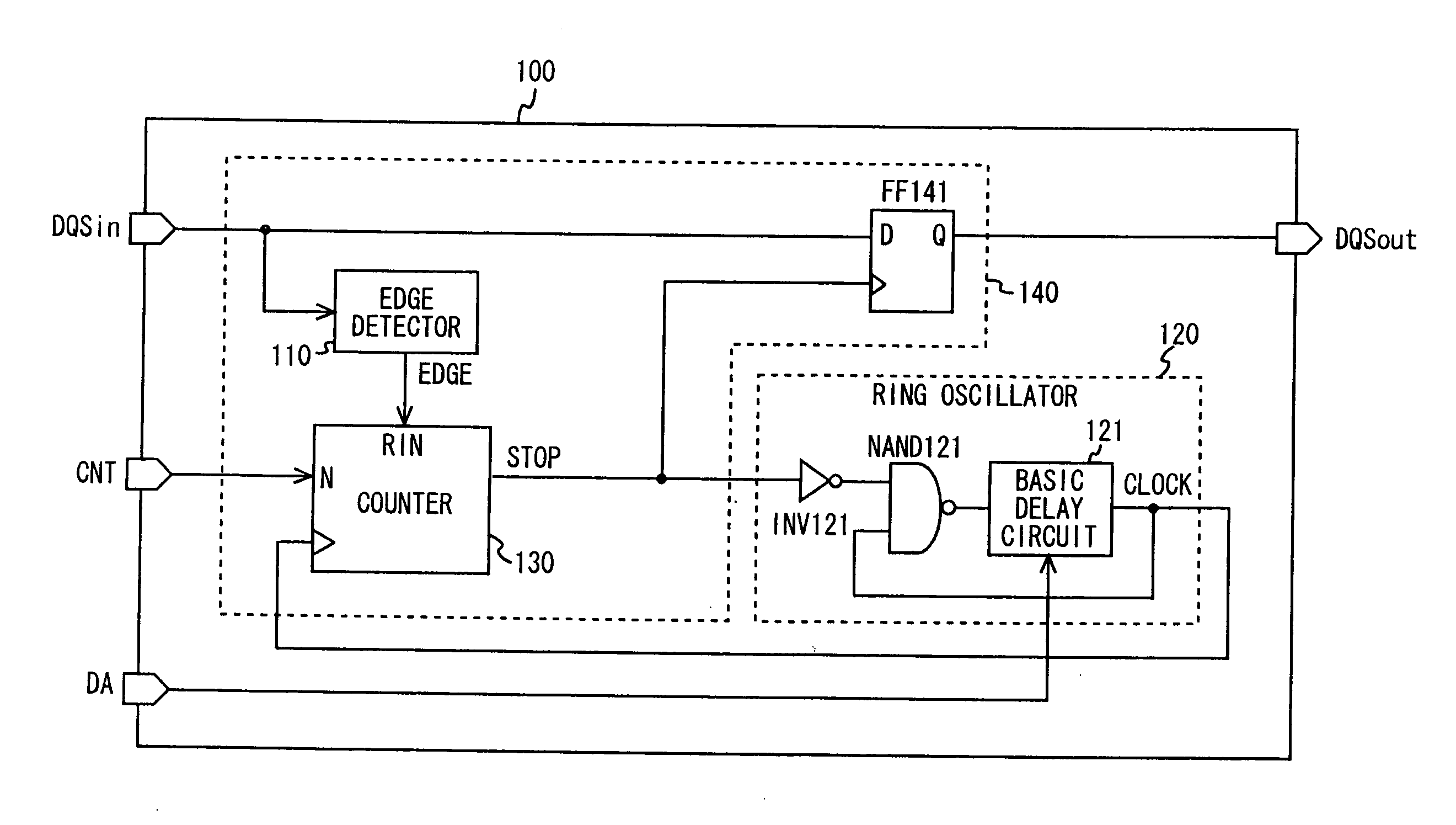
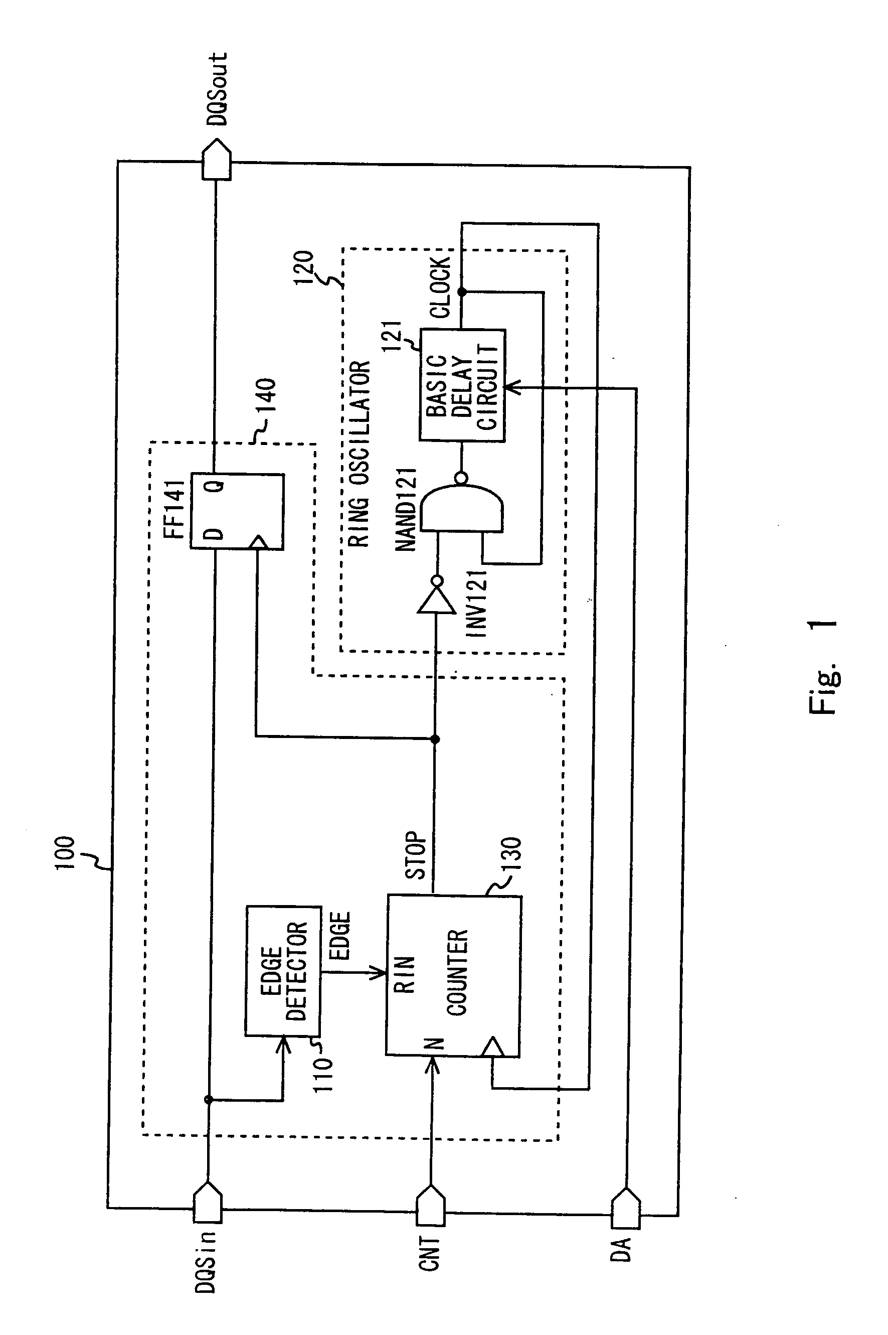
[0030]A first exemplary embodiment of the present invention is described hereinafter in detail with reference to the drawings. In the first exemplary embodiment, the present invention is applied to a delay circuit of a memory interface. FIG. 1 shows an example of a configuration of a delay circuit 100 according to the first exemplary embodiment. Referring to FIG. 1, the delay circuit 100 includes an input terminal DQSin, an output terminal DQSout, a count number setting terminal CNT, a delay amount setting terminal DA, a ring oscillator 120 and a control circuit 140. The control circuit 140 includes an edge detector 110, a counter 130 and a flip-flop FF141. A signal input to the input terminal DQSin is referred to as a data strobe signal DQSin, and a signal output from the output terminal DQSout is referred to as a data strobe signal DQSout.
[0031]The input terminal DQSin is a terminal to which the data strobe signal DQSin having a bandwidth with a frequency of several tens to severa...
second exemplary embodiment
[0054]A second exemplary embodiment of the present invention is described hereinafter in detail with reference to the drawings. In the second exemplary embodiment, like the first exemplary embodiment, the present invention is applied to a delay circuit of a memory interface. FIG. 7 shows an example of a configuration of a delay circuit 200 according to the second exemplary embodiment. Referring to FIG. 7, the delay circuit 200 includes an input terminal DQSin, an output terminal DQSout, a count number setting terminal CNT, a delay amount setting terminal DA, a ring oscillator 120 and a control circuit 150. The control circuit 150 includes an edge detector 110, a counter 130, a flip-flop FF151, a latch circuit SRL151 and an inverter INV151. In FIG. 7, the elements denoted by the same reference symbols as those in FIG. 1 have the same or similar configuration as the equivalents in FIG. 1. The second exemplary embodiment is different from the first exemplary embodiment in the configura...
third exemplary embodiment
[0069]A third exemplary embodiment of the present invention is described hereinafter in detail with reference to the drawings. In the third exemplary embodiment, like the first exemplary embodiment, the present invention is applied to a delay circuit of a memory interface. FIG. 10 shows an example of a configuration of a delay circuit 300 according to the third exemplary embodiment. Referring to FIG. 10, the delay circuit 300 includes an input terminal DQSin, an output terminal DQSout, a count number setting terminal CNT, a delay amount setting terminal DA, a ring oscillator 160 and a control circuit 170. The control circuit 170 includes an edge detector 110, a counter 130, and a high-through latch circuit HL171. In FIG. 10, the elements denoted by the same reference symbols as those in FIG. 1 have the same or similar configuration as the equivalents in FIG. 1. The third exemplary embodiment is different from the first exemplary embodiment in the configuration of the control circuit...
PUM
 Abstract
Description
Claims
Application Information