Antenna switching device and method thereof

a switching device and antenna technology, applied in the direction of selective content distribution, television system scanning details, television systems, etc., can solve the problem that the device cannot receive an oob (out of band) signal

Inactive Publication Date: 2005-10-27
PANASONIC CORP
View PDF13 Cites 30 Cited by
  • Summary
  • Abstract
  • Description
  • Claims
  • Application Information

AI Technical Summary

Problems solved by technology

However, a problem exists in the conventional antenna switch apparatus; when the antenna switch apparatus is selecting a terrestrial broadcasting channel, the device can not receive an OOB (Out Of Band) signal which includes channel information of a cable broadcasting channel.

Method used


Image

  • Antenna switching device and method thereof
  • Antenna switching device and method thereof
  • Antenna switching device and method thereof

Examples


first exemplary embodiment

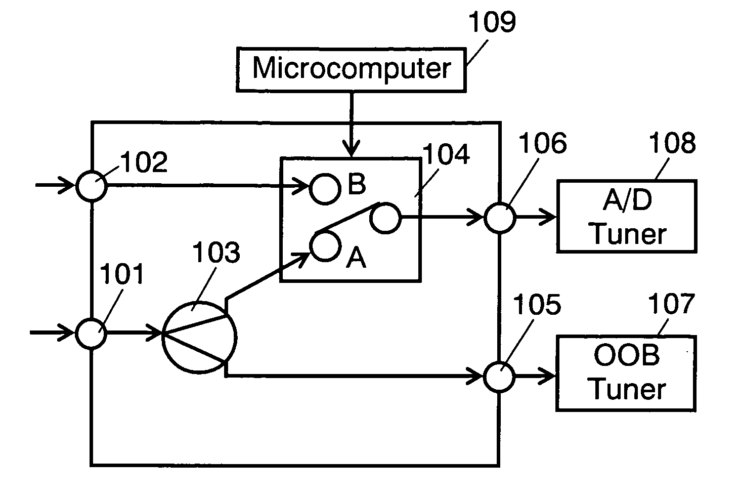
[0026]FIG. 1 is a block diagram showing a constitution of an antenna switch apparatus in accordance with a first exemplary embodiment of the present invention. A working principle of the antenna switch apparatus is explained hereinafter. In FIG. 1, when an cable for a cable broadcasting is connected to first antenna input terminal 101 and an antenna for a terrestrial broadcasting is connected to second antenna input terminal 102, the cable broadcasting signal input to first antenna input terminal 101 is split into two signals at first splitter 103. The split signals are a first cable broadcasting signal and a second cable broadcasting signal. The first cable broadcasting signal is input to selector 104, and the second cable broadcasting signal is input to OOB (out of band) tuner 107 through first output terminal 105.

[0027] Along the cable broadcasting signal, an in-band signal and an OOB signal are multiplexed. Generally, in-band signal includes a picture signal and a sound signal,...

second exemplary embodiment

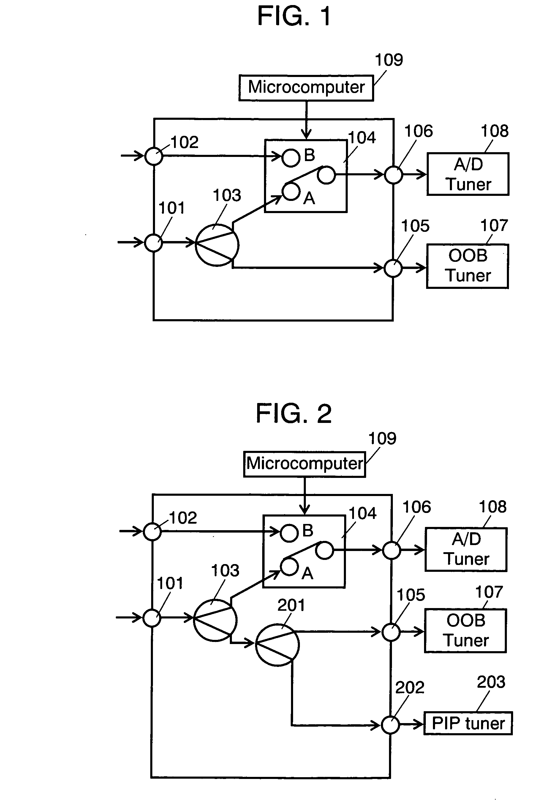
[0039]FIG. 2 is a block diagram showing a constitution of an antenna switch apparatus in accordance with a second exemplary embodiment of the present invention. As shown in FIG. 2, the antenna switch apparatus according to the exemplary embodiment includes second splitter 201, third output terminal 202 and PIP tuner 203 in addition to constitutional members of the first exemplary embodiment. Each block identical to that of in FIG. 1 has the same numeral and detailed explanation of it is omitted.

[0040] A second cable broadcasting signal output from first splitter 103 is input to second splitter 201. Second splitter 201 splits the second cable broadcasting signal and outputs a third cable broadcasting signal and a fourth cable broadcasting signal. The third cable broadcasting signal is output through first output terminal 105 to OOB tuner 107. The fourth cable broadcasting signal is output through third output terminal 202 to PIP tuner 203 making two picture displays possible. The PI...


PUM


Abstract

An antenna switch apparatus and a switching method thereof including an antenna-input for cable broadcasting and an antenna-input for terrestrial broadcasting and satellite broadcasting, always receiving an OOB signal, and freely selecting one of a cable broadcasting channel and a terrestrial broadcasting channel or a satellite broadcasting channel is provided. In the antenna switch apparatus and the switching method, the terrestrial broadcasting signal is input to a select means, the cable broadcasting signal is split by a split means and the signals are input to an OOB tuner and the select means, then a signal selected by the select means is input to an A/D tuner. With this arrangement, one of the signal of the cable broadcasting channel and the terrestrial broadcasting channel or the satellite broadcasting is selected while keep receiving the OOB signal.

Description

TECHINICAL FIELD [0001] The present invention relates to an antenna switch apparatus to be used for a television receiver, and a switching method thereof. BACKGROUND ART [0002] Presently, broadcasting is classified into three categories: terrestrial broadcasting, satellite broadcasting and cable broadcasting; and there are a variety of modulation methods available for the broadcasting waves. Under such circumstances, an antenna switch apparatus having a plurality antenna input terminals is developed. [0003]FIG. 4 shows a constitution of a conventional antenna switch apparatus. In FIG. 4, a cable for a cable-broadcasting is connected to first antenna input terminal 401 and a cable for a terrestrial broadcasting is connected to second input terminal 402. If a subscriber selects a cable broadcasting channel, microcomputer 406 controls selector 403 to close to a point A, then the cable broadcasting signal is output to A / D tuner 405 through second output terminal 404. The A / D tuner is a ...

Claims


Application Information

Patent Timeline
Patent Type & Authority Applications(United States)
IPC IPC(8): H04B1/18H04B1/44H04N5/44H04N5/46H04N7/10
CPCH04B1/44H04N5/44H04N5/4401H04N5/46H04N21/6143H04N21/4316H04N21/4622H04N21/6112H04N21/6118H04N7/104H04N21/426
Inventor SASAKI, SHOGOMASUDA, YASUOKAWAKAMI, TSUYOSHITESHIMA, MISAO
Owner PANASONIC CORP
Why Eureka
Try Eureka