Dual adjustable feather jig

Inactive Publication Date: 2005-11-03
SCHWARTZ NEAL K
View PDF25 Cites 23 Cited by
  • Summary
  • Abstract
  • Description
  • Claims
  • Application Information

AI Technical Summary

Benefits of technology

[0013] During use, the lower and upper feather boards are adjusted so that the piece of wood stock may be simultaneously held against the rip fence and forced downward against the top surface of a worktable. Because the ‘T’ channel bar is designed to fit into a standard ‘T’ slot, the jig to be used on an

Problems solved by technology

Because many rip fences used today are not securely held down at both ends to the worktable, mounting a vertical feather board to the rip fence is undesirable because the rip fence may rise off the worktable.
Also, it is impossible to lateral reposition the vertical fe

Method used


Image

  • Dual adjustable feather jig
  • Dual adjustable feather jig
  • Dual adjustable feather jig

Examples


Embodiment Construction

)

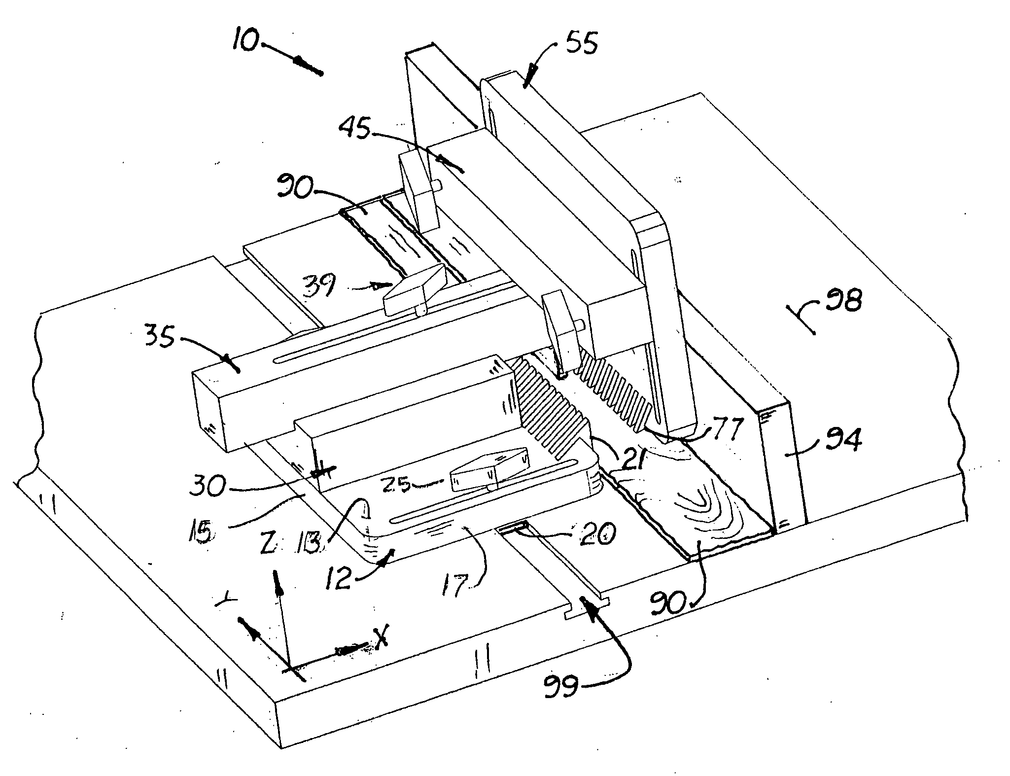
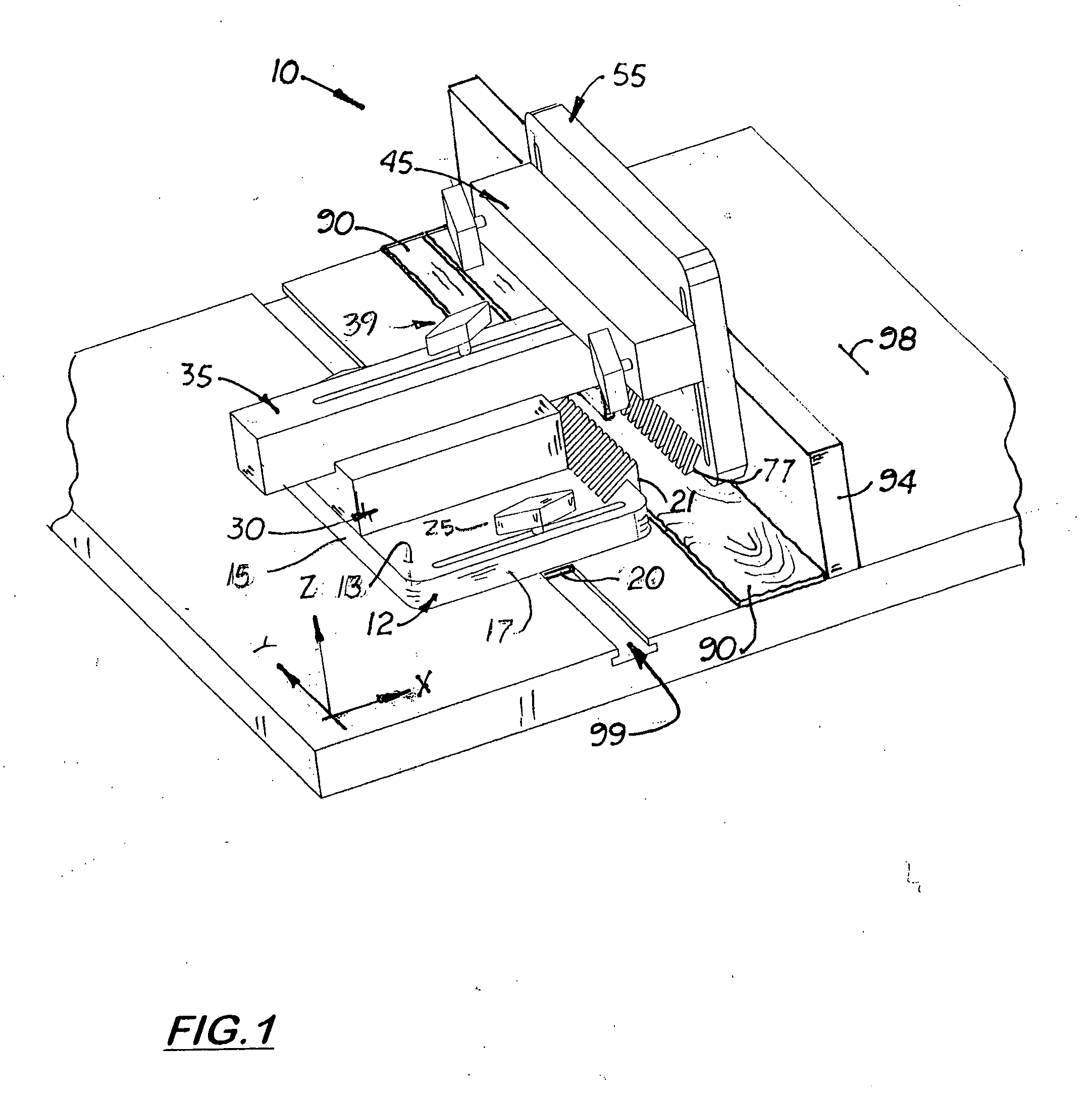
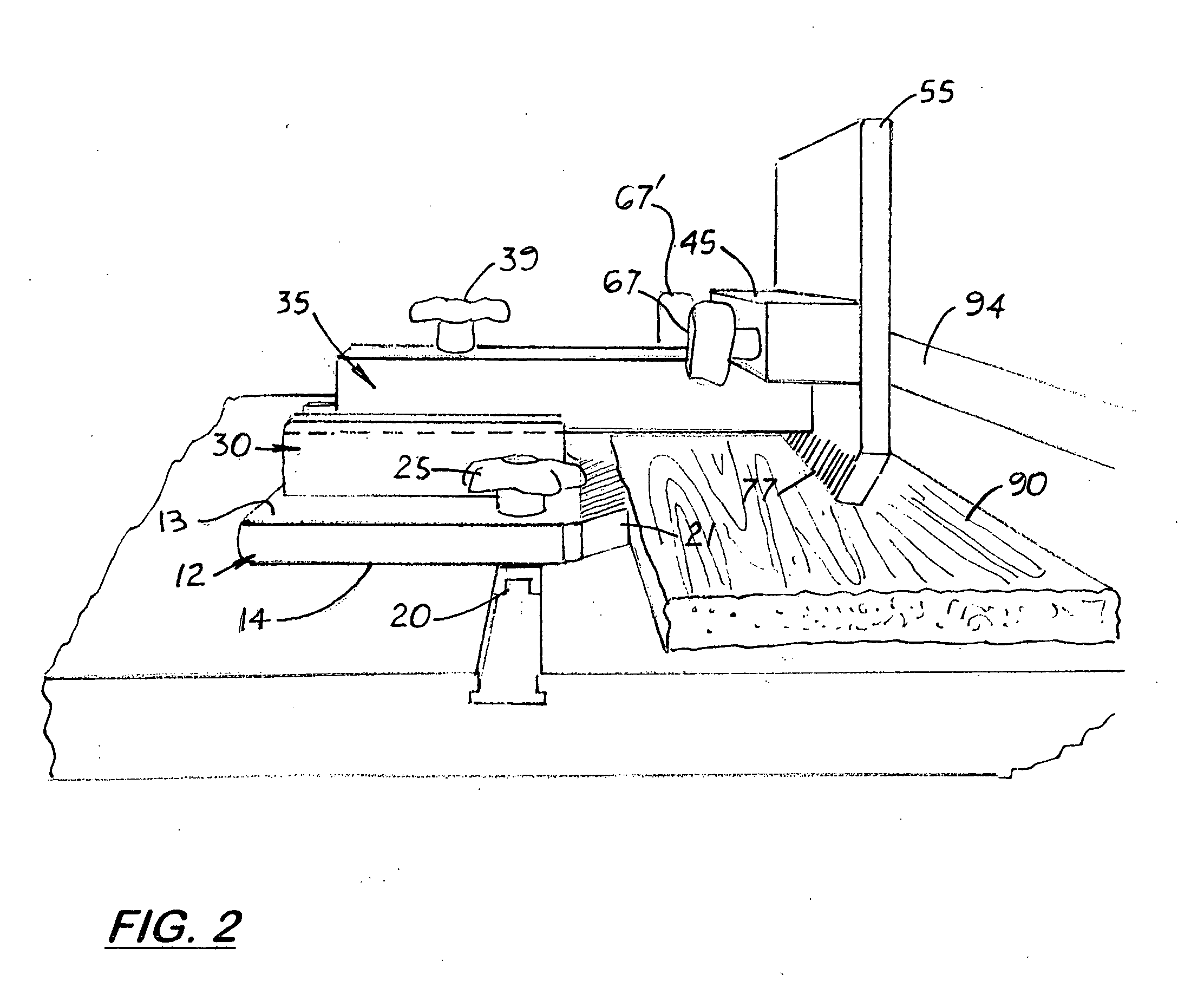
[0018] Shown in the accompanying Figs is an adjustable dual feather jig 10 for simultaneously holding a piece of wood stock 90 firmly against the lateral surface of a rip fence 94 and holding the piece of wood stock 90 firmly downward against the top surface of a worktable 98.

[0019] The feather jig 10 disclosed includes a horizontally aligned lower feather board 12 which is slidingly attached to a worktable 98, such as a table saw, router table, or shaper table. The lower feather board 12 includes a planar top surface 13, a planar bottom surface 14, left vertical edge 15, a front vertical edge 17, and a back vertical edge 18. Aligned on the bottom surface 14 and extending from the front vertical edge 17 to the back vertical edge 18 is a ‘T’ channel bar 20. The “T channel bar 20 is designed to slide freely into a standard ‘T’ slot 99 formed on the worktable 98 that is aligned parallel to the rip fence 94 or saw blade (not shown). The ‘T’ slot 99 is approximately 3 / 4 inches wide and...


PUM

PropertyMeasurementUnit
Heightaaaaaaaaaa

Abstract

A dual adjustable feather jig for simultaneously holding a wood piece firmly against a stationary rip fence and against the top surface of the worktable. The feather jig includes a lower feather board with a ‘T’ channel bar adjustably mounted on the bottom surface of the lower feather board capable of engaging the ‘T’ slot formed on a standard worktable. The ‘T’ channel is adjustably mounted on the lower feather board to allow the lower feather board to move laterally (X direction) over the worktable when the ‘T’ channel bar is inserted into the ‘T’ slot. Mounted transversely on the lower feather board is an upper feather board assembly that includes a vertical feather board designed to be extended over a piece of wood stock to hold it down against the worktable. The vertical feather board is connected to a slider arm that slides longitudinally over a riser board securely mounted to the top surface of the lower feather board. Formed on a lateral edge and lower edges of the lower and upper feather boards, respectively, are two sets of diagonally aligned fingers that press against a piece of wood stock against a standard rip fence and against the top surface of the worktable.

Description

[0001] This utility patent application claims the benefit of provisional patent application (Ser. No. 60 / 567,617) filed on May 3, 2004.BACKGROUND OF THE INVENTION [0002] 1. Field of the Invention [0003] 2. Description of the Related Art [0004] Table saws and router tables (herein after often include a rip fence attached to the top surface of the table and parallel to the saw blade. Most worktables also include a ‘T’ slot formed on the top surface of the table that extends parallel to the rib fence and on the side of the saw blade or router bit opposite the rip fence. The ‘T’ slot is designed to receive a ‘T’ channel attached to the bottom surface of a miter guide that is used to push the wood stock towards the saw blade or router bit. [0005] Heretofore, adjustable feather boards have been used on table saws to ‘cut’ a piece of wood stock in a longitudinal direction parallel with the grain. Feather boards typically include a set of fingers located along one edge that press the piece ...

Claims


Application Information

Patent Timeline
IPC IPC(8): B23D47/04B26D7/06B27B29/00B27C5/06
CPCB23D47/04B27C5/06B27B29/00Y10T83/727Y10T83/741Y10T83/743Y10T83/744Y10T83/747Y10T83/7713
Inventor SCHWARTZ, NEAL K.
Owner SCHWARTZ NEAL K
Why Eureka
Try Eureka