Floor box and cover therefor

a floor box and cover technology, applied in the field of floor boxes, can solve the problems of many prior art floor fixtures not designed to withstand heavy loads, and the floor fixtures are often not designed to exclude scrub water or floor cleaning solutions, and achieve the effect of preventing backflow

Inactive Publication Date: 2005-11-10
THE WIREMOLD CO
View PDF24 Cites 19 Cited by
  • Summary
  • Abstract
  • Description
  • Claims
  • Application Information

AI Technical Summary

Benefits of technology

[0011] A drain opening is preferably provided in one of the housing walls, usually the bottom wall for receiving a drain fitting and coupling a drainpipe to the housing. In a preferred embodiment, a check valve is provided in-line with the drainpipe for preventing back flow from entering the interior space defined by the housing.
[0012] The housing is designed

Problems solved by technology

Further, prior art floor fixtures are often not designed to exclude scrub water or floor cleaning solutions from entering the fixtures.
Additionally, m

Method used


Image

  • Floor box and cover therefor
  • Floor box and cover therefor
  • Floor box and cover therefor

Examples


Embodiment Construction

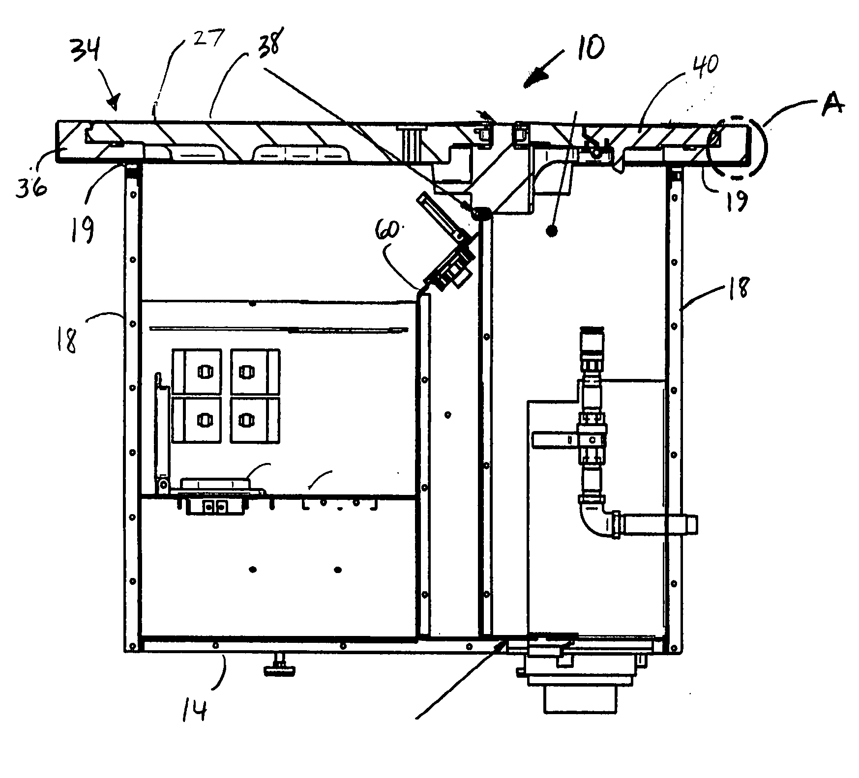
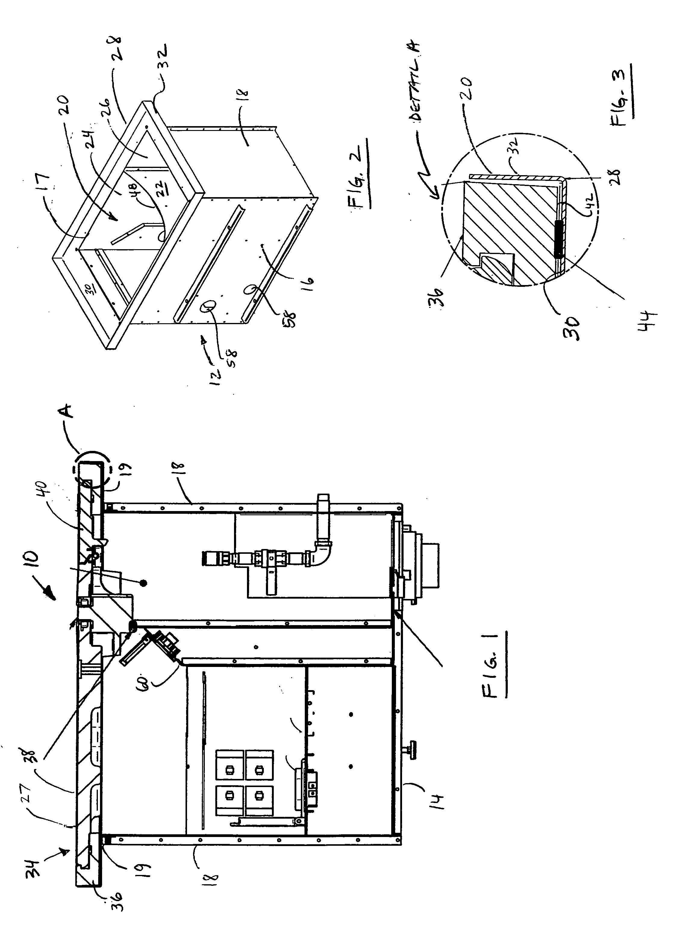
[0048] Referring to FIGS. 1-3, a floor box 10 includes a rectangular housing 12 having a bottom wall 14, a pair of side walls 16 and a pair of end walls 18. The side walls 16 and end walls 18 extend generally perpendicular from the bottom wall 14 and cooperate therewith to define an interior space 20.

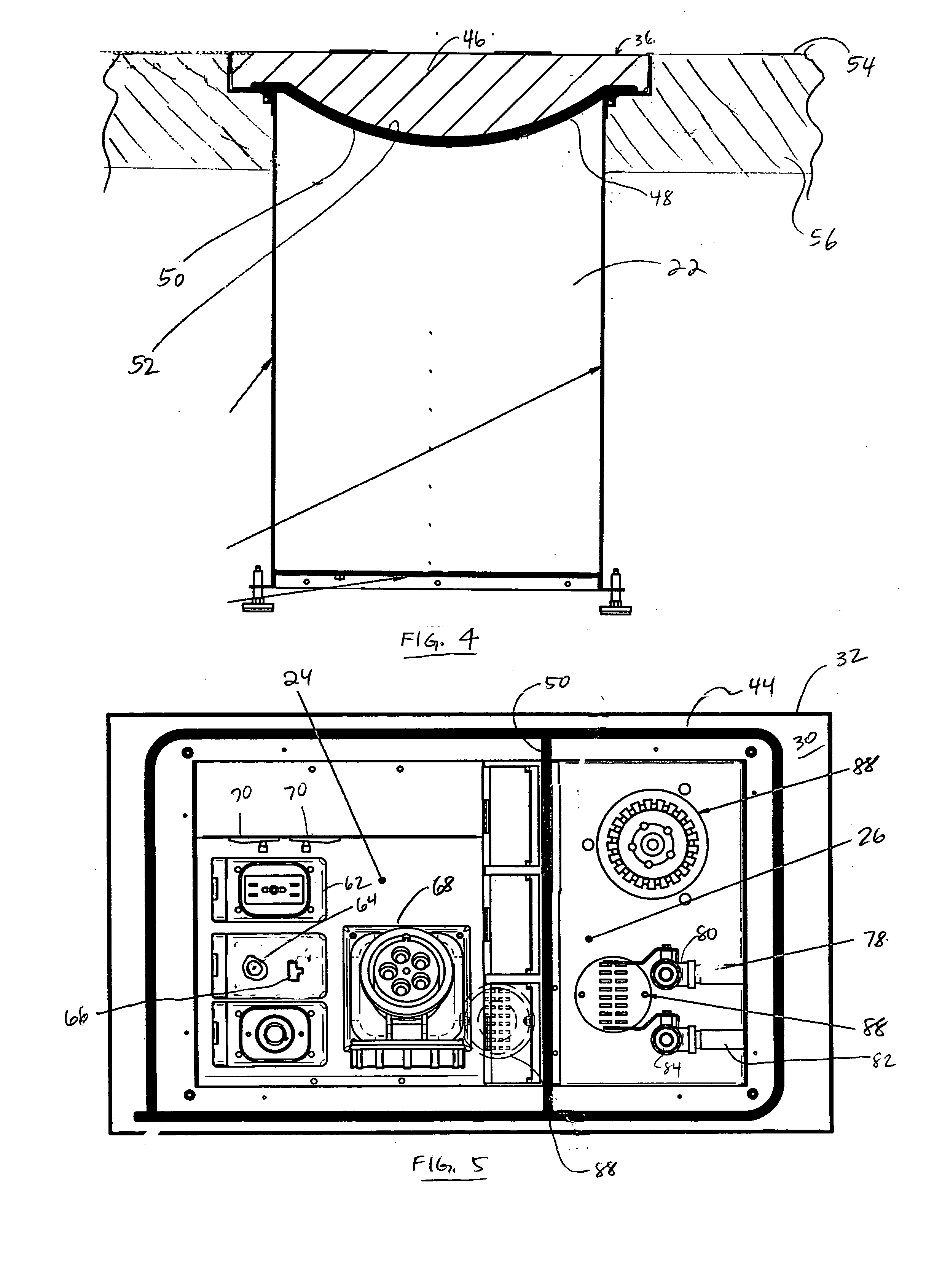
[0049] A partition wall 22 attached to side walls 16, 16 and bottom wall 14 partially divides the interior space 20 into first and second compartments 24 and 26 respectively. A sealant (not shown) such as a gasket material or silicone can be used to seal the joints between the partition wall 22 and the side walls 16, 16 and the partition wall and the bottom wall 14 such that the first and second compartments 24 and 26 respectively, are sealed one from the other. Depending on the sealer used, air, liquids, dirt as well as other materials are prevented from passing between the first compartment 24 and the second compartment 26. Alternatively, in other embodiments of the present invention...


PUM


Abstract

A floor box for providing access to multiple utilities in a floor structure. The floor box includes a housing having a bottom wall and one or more side walls extending from the bottom wall and defining an interior space therebetween. A partition wall attached to the bottom wall and the side walls partially divides the interior space. A flange is attached at the upper edges of the side walls and includes a surface extending outwardly therefrom. A cover assembly includes a frame mounted to the flange. The frame has a cross member overlying the partition wall and cooperating therewith to divide the interior space into first and second compartments. The cover assembly further includes first and second access doors movable relative to the frame between open and closed positions for providing access to the first and second compartments respectively. A gasket seals the first and second compartments.

Description

CROSS REFERENCE TO RELATED APPLICATIONS [0001] This application claims priority to U.S. Provisional Patent Application No. 60 / 569,191 filed on May 7, 2004 entitled “Hinged Cover Assembly For In-Floor Fitting”. The disclosure of the above-identified provisional application is incorporated herein by reference. Additionally, the present application represents an improvement of that disclosed in U.S. Pat. No. 6,462,277 entitled “Cover Assembly For An In-Floor Fitting”. Said U.S. Pat. No. 6,462,277 is incorporated by reference herein.FIELD OF THE INVENTION [0002] The present invention generally relates to a floor box for providing access to utilities in a floor structure, and more particularly to a floor box having separate sealed compartments for providing access to multiple utilities at a floor structure. BACKGROUND OF THE INVENTION [0003] Often, large buildings such as convention centers, exhibition centers, arenas and other facilities provide utility services at certain locations thr...

Claims


Application Information

Patent Timeline
IPC IPC(8): B60R9/00E04B5/48E04C2/52E04F15/024H02G3/18H02G9/10
CPCE04B5/48H02G9/10H02G3/185E04F15/024
Inventor MACMILLAN, GEOFF D.ZIEGLER, PAUL W.HALLIDAY, ANDREW JAMESSUTTON, NEIL
Owner THE WIREMOLD CO
Why Eureka
Try Eureka