Shaft seal assembly and method

a technology of shaft seals and seal assemblies, which is applied in the direction of engine seals, leakage prevention, machines/engines, etc., can solve the problems of excessive seal wear and negatively affect the performance or safety of turbopumpe, and achieve the effect of reducing heat and wear in the seal assembly and sufficient sealing

Active Publication Date: 2005-11-10
THE BOEING CO +1
View PDF16 Cites 20 Cited by
  • Summary
  • Abstract
  • Description
  • Claims
  • Application Information

AI Technical Summary

Benefits of technology

[0008] The present invention provides a pressure-actuated shaft seal assembly and associated method for controlling the flow of fluid adjacent a rotatable shaft. The seal assembly includes one or more seal members that can be adjusted between open and closed positions, for example, according to the rotational speed of the shaft. Thus, the heat and wear in the seal assembly can be minimized during high speed operation, while a sufficient seal is maintained during both low and high speed operation.

Problems solved by technology

However, due to the high rotational speed of the components of the turbopump, contact between the stationary seals and the rotating shaft can result in excessive wear of the seals as well as the generation of heat that can negatively affect the performance or safety of the turbopump.

Method used


Image

  • Shaft seal assembly and method
  • Shaft seal assembly and method
  • Shaft seal assembly and method

Examples


Embodiment Construction

[0019] The present invention now will be described more fully hereinafter with reference to the accompanying drawings, in which preferred embodiments of the invention are shown. This invention may, however, be embodied in many different forms and should not be construed as limited to the embodiments set forth herein; rather, these embodiments are provided so that this disclosure will be thorough and complete, and will fully convey the scope of the invention to those skilled in the art. Like numbers refer to like elements throughout.

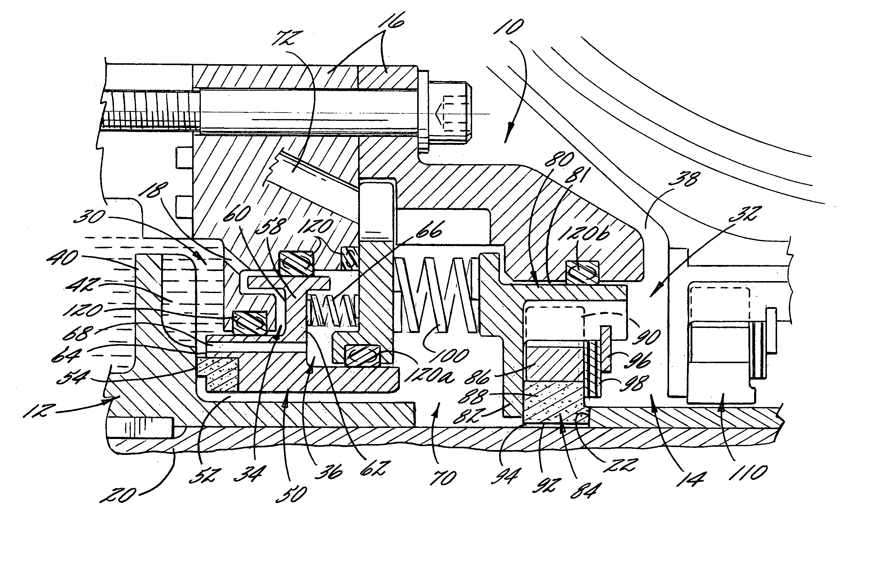
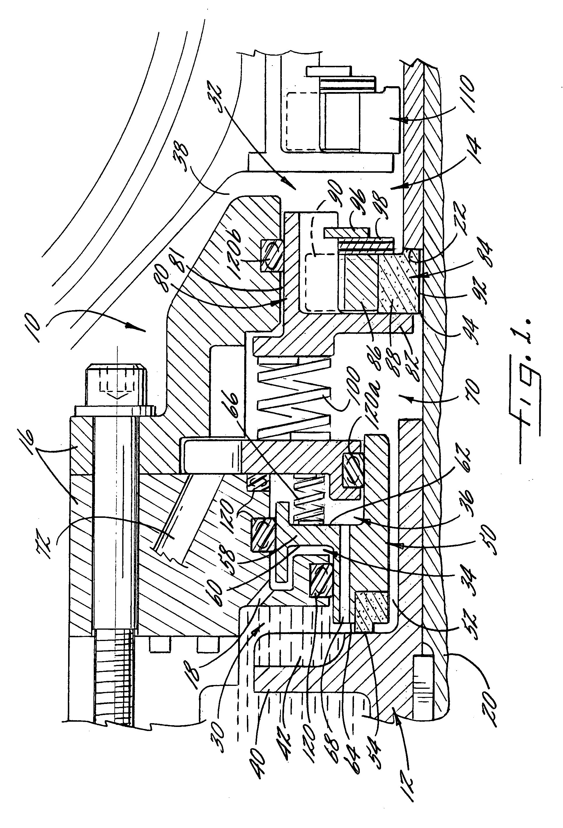
[0020] Referring to FIG. 1, there is shown a pressure-actuated shaft seal assembly 10 according to one embodiment of the present invention. The seal assembly 10 can be used for forming a seal between first and second sides 12, 14 of the seal assembly 10. For example, the seal assembly 10 can be used in a turbopump for a rocket engine with the first side 12 directed toward the pump and the second side 14 directed toward the turbine of the turbopump so tha...


PUM


Abstract

A pressure-actuated shaft seal assembly and associated method for controlling the flow of fluid adjacent a rotatable shaft are provided. The seal assembly includes one or more seal members that can be adjusted between open and closed positions, for example, according to the rotational speed of the shaft. For example, the seal member can be configured to be adjusted according to a radial pressure differential in a fluid that varies with the rotational speed of the shaft. In addition, in the closed position, each seal member can contact a rotatable member connected to the shaft to form a seal with the rotatable member and prevent fluid from flowing through the assembly. Thus, the seal can be closed at low speeds of operation and opened at high speeds of operation, thereby reducing the heat and wear in the seal assembly while maintaining a sufficient seal during all speeds of operation.

Description

FEDERALLY SPONSORED RESEARCH OR DEVELOPMENT [0001] The invention described herein was made in the performance of work under NASA contract No. NAS8-01107 and is subject to the provisions of Section 305 of the National Aeronautics and Space Act of 1958 (72 Stat. 435; 42 U.S.C. 2457).BACKGROUND OF THE INVENTION [0002] 1) Field of the Invention [0003] This invention relates to seal assemblies and, in particular, to a pressure-actuated seal assembly for controlling the flow of a fluid along a shaft. [0004] 2) Description of Related Art [0005] Various applications require the formation of a seal along a shaft or other rotatable member. For example, turbopumps that are used in rocket engines typically include a turbine and a pump that are connected by a shaft. The turbine is rotated by the flow of a fluid, thereby rotating the pump, which pumps another fluid. In some cases, it is desirable or necessary to separately maintain the fluids in the turbine and the pump. For example, leakage of a...

Claims


Application Information

Patent Timeline
Patent Type & Authority Applications(United States)
IPC IPC(8): F16J15/00F16J15/16F16J15/34
CPCF16J15/004F16J15/3448F16J15/3404F16J15/164
Inventor KEBA, JOHN E.
Owner THE BOEING CO
Why Eureka
Try Eureka