Eureka AIR delivers breakthrough ideas for toughest innovation challenges, trusted by R&D personnel around the world.

Cylinder head cover for a cylinder head of an internal combustion engine

a technology for internal combustion engines and cylinder heads, which is applied in the direction of machines/engines, sealing, lubrication of auxillaries, etc., can solve the problems of increased weight of cylinder heads, increased costs, and reduced seal tightness

Inactive Publication Date: 2008-10-28
MANN HUMMEL GMBH +1
View PDF3 Cites 30 Cited by
  • Summary
  • Abstract
  • Description
  • Claims
  • Application Information

AI Technical Summary

Benefits of technology

[0007]It is an object of the present invention to provide an improved cylinder head cover for the cylinder head of an internal combustion engine.
[0008]Another object of the invention is to provide a cylinder head cover which can be secured to a cylinder head in a simple manner while reliably assuring adequate sealing between the cover and the cylinder head over a long period of operation.
[0013]This has the result, on the one hand, that the sealing element is subject only to minor stress in vertical direction, i.e., in the direction of the attachment force. On the other hand, because of the low magnitude of the attachment force, only a few connecting elements are required, and the connecting elements can furthermore be of a simple design, e.g., clips or snap-in hooks injection molded onto the cylinder head cover.
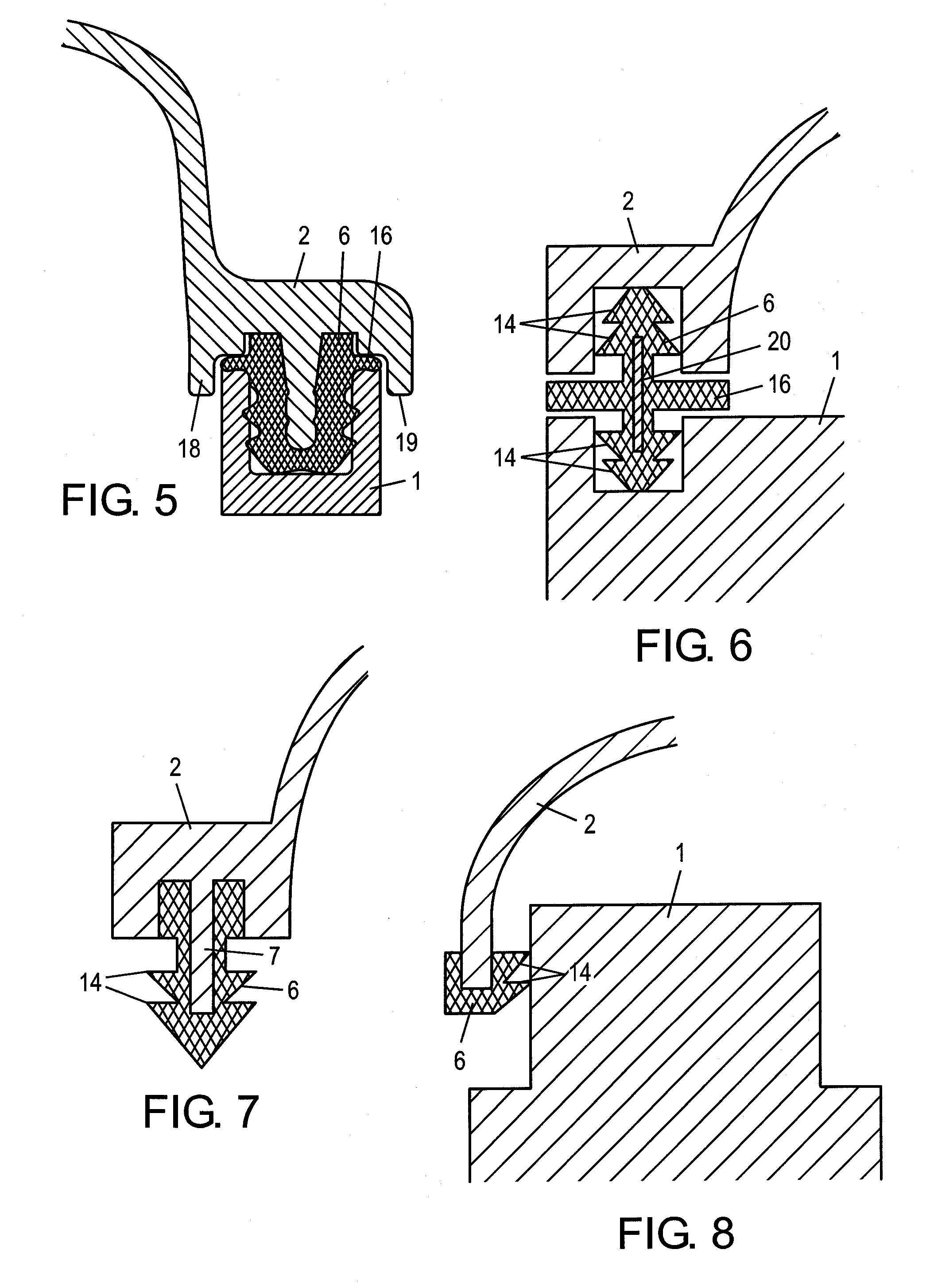
[0014]The sealing element can be configured in such a way that it is capable, in addition to the connecting elements, of transmitting a clamping force that acts in the direction of the attachment force of the connecting elements which hold the cylinder head cover to the cylinder head. This can be realized, for example, by the sealing element having one or more locking projections on its lateral surface, which are inserted into recesses in the cylinder head cover or the cylinder head and which function as barbs. Due to this capability of transmitting a clamping force running approximately perpendicular to the sealing force, the sealing element makes it possible to minimize the number of connecting elements or reduce them to a particularly simple design with a mounting function. This can be realized, for example, by a simple form-fit connection between the cylinder head cover and the cylinder head.
[0015]A support member may be incorporated in the sealing element, with the support member being at least partially or possibly even fully enclosed by the sealing element. This support member can be firmly connected to either the cylinder head or the cylinder head cover or, according to another embodiment, form a support core that is a component of the sealing element and is not connected to the cylinder head or the cylinder head cover. The support core stabilizes the sealing element so as to prevent the sealing element from yielding laterally, particularly during mounting of the cylinder head cover to the cylinder head.

Problems solved by technology

This involves the risk, however, that seal tightness will also decrease.
Both of these measures, however, add weight to the cylinder head cover and are associated with additional costs.

Method used


Image

  • Cylinder head cover for a cylinder head of an internal combustion engine
  • Cylinder head cover for a cylinder head of an internal combustion engine
  • Cylinder head cover for a cylinder head of an internal combustion engine

Examples


Embodiment Construction

[0029]In the figures, like components are identified by the same reference numerals.

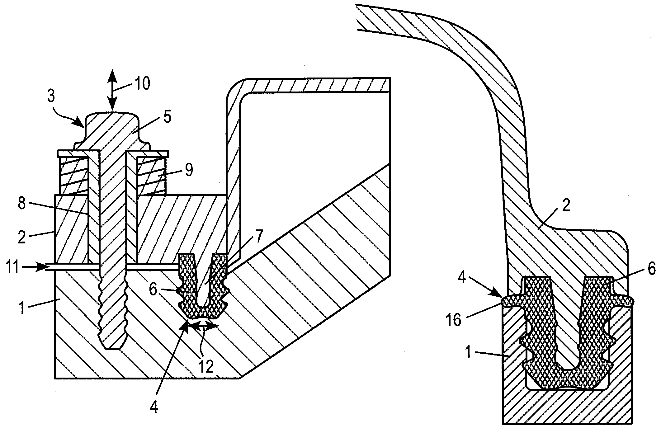
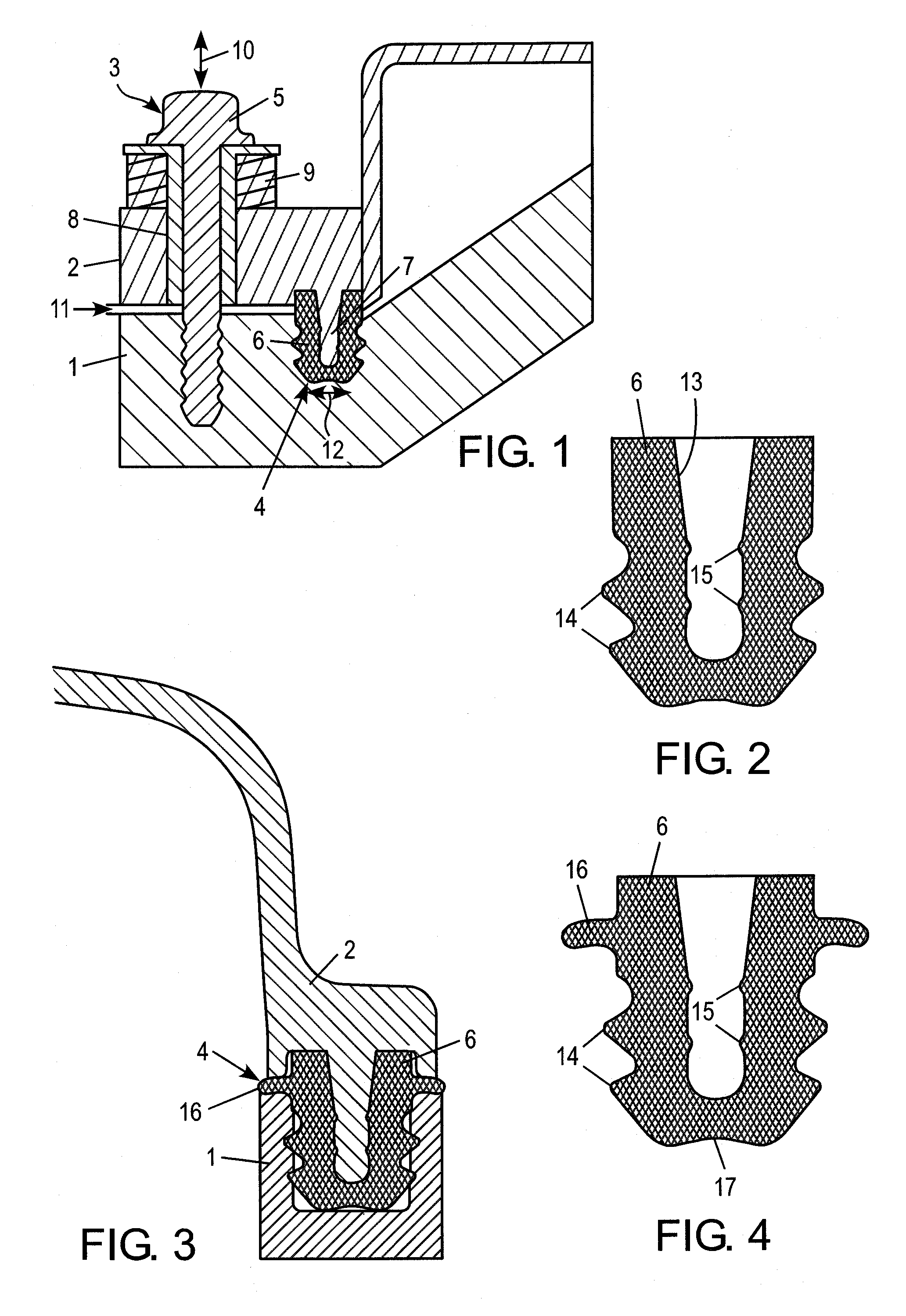
[0030]FIG. 1 shows a cylinder head 1 of an internal combustion engine with mounted cylinder head cover 2, which is held to the cylinder head 1 in an outer connecting region 3. Separate therefrom and offset inwardly is a sealing region 4 between the cylinder head 1 and the cylinder head cover 2, which comprises a circumferential sealing element 6 that is inserted into a peripheral groove formed in the top of the cylinder head. The cross-section of sealing element 6 is cup-shaped, and a support member 7 formed integrally with the cylinder head cover 2 projects into the interior of the sealing element 6. The sealing element 6 is slipped onto the support member 7 to obtain a pre-assembled unit. The sealing element 6 extends all around adjacent the outer margin of the cylinder head cover, providing a circumferential seal between the cylinder head and the cylinder head cover.

[0031]The connection between th...


PUM


Abstract

A cover for a cylinder head of an internal combustion engine having a connecting element for attachment the cylinder head and a sealing element arranged between the cylinder head cover and the cylinder head. The connecting element is associated with a connecting area, and the sealing element is associated with a sealing area. The connecting area and the sealing area are constructed independently of each other and are spatially separated from each other, and the force vectors of the connecting force transmitted by the connecting element and the sealing force transmitted by the sealing element form an angle with each other.

Description

CROSS REFERENCE TO RELATED APPLICATIONS[0001]This application is a continuation of international patent application no. PCT / CP2005 / 054092, filed Aug. 19, 2005, designating the United States of America and published in German on Mar. 2, 2006 as TWO 2006 / 021545, the entire disclosure of which is incorporated herein by reference. Priority is claimed based on Federal Republic of Germany patent application no. DE 10 2004 040 656.1, filed Aug. 20, 2004.BACKGROUND OF THE INVENTION[0002]The present invention relates to a cylinder head cover for a cylinder head of an internal combustion engine.[0003]Known cylinder head covers are placed on the cylinder head of an internal combustion engine and are secured to the cylinder head by attachment bolts. The attachment bolts are usually guided through attachment lugs formed on the cylinder head cover and are screwed together with the underlying cylinder head to secure the cover. To obtain a fluid-tight seal, a circumferential gasket is inserted into...

Claims


Application Information

Patent Timeline
Patent Type & Authority Patents(United States)
IPC IPC(8): F01P1/04
CPCF02F7/006Y10S277/916F02F7/00F16J15/06
Inventor JESSBERGER, THOMASKLAMERT, INESKOCH, INGOKORN, ALEXANDERSCHLEIDEN, THOMASWEBER, ANDREASDAIBER, MICHAELGESSNER, KLAUSWALZ, TIMOSALAMEH, RALFSCHNEIDER, WILHELMWESTPHAL, DANIEL
Owner MANN HUMMEL GMBH
Why Eureka
Eureka Blog
Learn More