Piezoelectric Pump

a technology of pump and piezoelectric pump, which is applied in the direction of pump parameter, positive displacement liquid engine, machine/engine, etc., can solve the problems of insufficient fluid transportation, inability to transport fluid, and reduced reliability of check valves, so as to achieve reliable discharge, efficient bent, and increased discharging pressure

Inactive Publication Date: 2009-06-11
MURATA MFG CO LTD
View PDF31 Cites 32 Cited by
  • Summary
  • Abstract
  • Description
  • Claims
  • Application Information

AI Technical Summary

Benefits of technology

[0013]Unlike Patent Document 3 in which fluid is pushed out by using an elastic restoring force of the diaphragm itself, according to the present invention, a metal plate having a high Young's modulus is used as the diaphragm and the fluid is discharged by forcibly bending the diaphragm by the piezoelectric element. In particular, since the piezoelectric element has a size such as to cover the first opening and such as not to reach the second opening, the portion of the diaphragm opposing the first opening and the portion of the diaphragm opposing the second opening can be efficiently bent in opposite directions. For this reason, the discharging pressure can be increased, and the fluid can be reliably discharged even under a condition where the pressure on the discharging side is high. In particular, since the diaphragm is formed by the metal plate having a high Young's modulus, it can properly follow the piezoelectric element, and this allows operation at a high frequency.
[0014]While the frequency of the voltage applied to the piezoelectric element can be arbitrarily selected, it is preferable that the piezoelectric element be driven at a frequency near the resonance frequency of a displacement member defined by the diaphragm and the piezoelectric element, since the displacement volume of the diaphragm is quite large, and a high flow rate can be obtained. When driving is performed in a primary resonance mode (first resonance frequency), fluid can be drawn in from the first opening, and can be discharged from the second opening. When a tertiary resonance mode (tertiary resonance frequency) is used, fluid can be drawn in from the second opening, and can be discharged from the first opening. While driving can be performed at a high frequency in both the primary resonance mode and the tertiary resonance mode, in particular, when the tertiary resonance mode is used, operation can be performed at a quite high frequency that is about three times of that in the primary resonance mode. Since this allows driving at a frequency above an audible region, noise can be avoided. As for this, for example, when a soft material is used as the diaphragm, as in Patent Document 3, there is a time lag between displacement of the center portion of the diaphragm and displacement of the peripheral portion of the diaphragm. Therefore, the fluid pump in Patent Document 3 cannot be driven at a frequency higher than or equal to a frequency corresponding to the time lag. In contrast, since the piezoelectric pump of the present invention uses a metal plate having a high Young's modulus as the diaphragm, it can be driven at a high resonance frequency of the first resonance mode and the tertiary resonance mode. In particular, when driving is performed in a tertiary resonance mode beyond the human audible region, noise is not produced, and a high flow rate can be obtained. Further, since the displacement is small, stress generated in a fixed portion between the pump body and the diaphragm is reduced, and reliability is thereby improved. It is preferable that the Young's modulus of the diaphragm be 100 GPa or more. When the Young's modulus is 100 Gpa or more, a high follow-up ability is obtained when driving is performed in any of the primary resonance mode and the tertiary resonance mode. Moreover, since the loss during driving is small, the amount of generated heat is small, and the power efficiency is high.
[0015]The piezoelectric pump of the present invention is suited to transport compressible fluid such as air. When a piezoelectric pump discharges imcompressible fluid such as liquid, in general, check valves formed of a soft material, such as rubber or resin, are respectively provided at the inlet and the outlet, and a piezoelectric element is driven at a low frequency of about several tens of hertz. When such a piezoelectric pump is used as a pump for discharging compressible fluid such as air, the displacement amount of the piezoelectric element is quite small, and little fluid can be discharged. When the piezoelectric element is driven near the resonance frequency (primary resonance frequency or tertiary resonance frequency) of the displacement member defined by the diaphragm and the piezoelectric element, the maximum displacement can be obtained. However, since the resonance frequency is a high frequency of the order of kilohertz, the check valves cannot perform a follow-up operation. Since a check valve is not provided in the present invention, even when the piezoelectric element is driven at the frequency near the resonance frequency, imcompressible fluid can be efficiently transported without being restricted by the check valve. Further, there is no fear that operation failure will be caused by adhesion of dust or the like to the check valve, and a highly reliable piezoelectric pump can be provided.
[0016]It is preferable that the second opening be provided at a position where the diaphragm is maximally displaced in a tertiary resonance mode or outside the position. While the position where the diaphragm is maximally displaced in the tertiary resonance mode differs in accordance with the area ratio of the piezoelectric element and the diaphragm or the Young's modulus of the diaphragm, when the second opening (inlet) is provided at the position of maximum displacement or outside the position, a sufficient sealing ability of the second opening (inlet) can be obtained when discharging the fluid from the first opening (discharging port) in an operation cycle of the piezoelectric pump, and backflow of the fluid to be discharged can be prevented. This increases not only the discharging pressure, but also the discharging flow rate.
[0017]A plurality of the second openings may be provided on the same circumference centered on the first opening. When driving is performed in a tertiary resonance mode, the second opening serves as an inlet. If one second opening is provided, fluid does sometimes not rapidly flow into an annular pocket space formed between the pump body and the peripheral portion of the diaphragm, and a sufficient amount of fluid is not discharged. In contrast, when a plurality of second openings are provided on the same circumference, the fluid can rapidly flow into the annular pocket space, and the amount of discharged fluid can be increased.
[0018]According to the present invention, the piezoelectric element having a size such as to cover the first opening and such as not to reach the second opening is bonded to the center portion of the metal diaphragm, and the piezoelectric element is driven by a voltage having a predetermined frequency so that the portion of the diaphragm opposing the first opening and the portion of the diaphragm opposing the second opening are bent in opposite directions. Therefore, it is possible to increase the discharging pressure, and to reliably discharge the fluid even under the condition where the pressure on the discharging side is high. Moreover, the piezoelectric element can be formed only by the pump body and the diaphragm having the piezoelectric element bonded thereto, and an auxiliary component, such as a check valve, is unnecessary. This makes it possible to realize a small, thin, and highly reliable piezoelectric pump having a very simple structure.

Problems solved by technology

However, reliability of the check valves is reduced with use for a long period, and the fluid is not sufficiently transported because of adhesion of foreign substances, such as dust, to the check valves.
Further, when the piezoelectric element is driven at a high frequency, the check valves, to which foreign substances, such as dust, adhere, do not follow the driving, and transportation of the fluid is impossible.
Unfortunately, since a plurality of piezoelectric elements need to be arranged in a plane in the piezoelectric pump having this structure, the piezoelectric pump has a large size and a complicated structure.
Moreover, a driving circuit for sequentially driving the piezoelectric elements is complicated, and this increases the cost.
This makes it impossible to increase the discharging pressure.

Method used


Image

  • Piezoelectric Pump
  • Piezoelectric Pump
  • Piezoelectric Pump

Examples


first embodiment

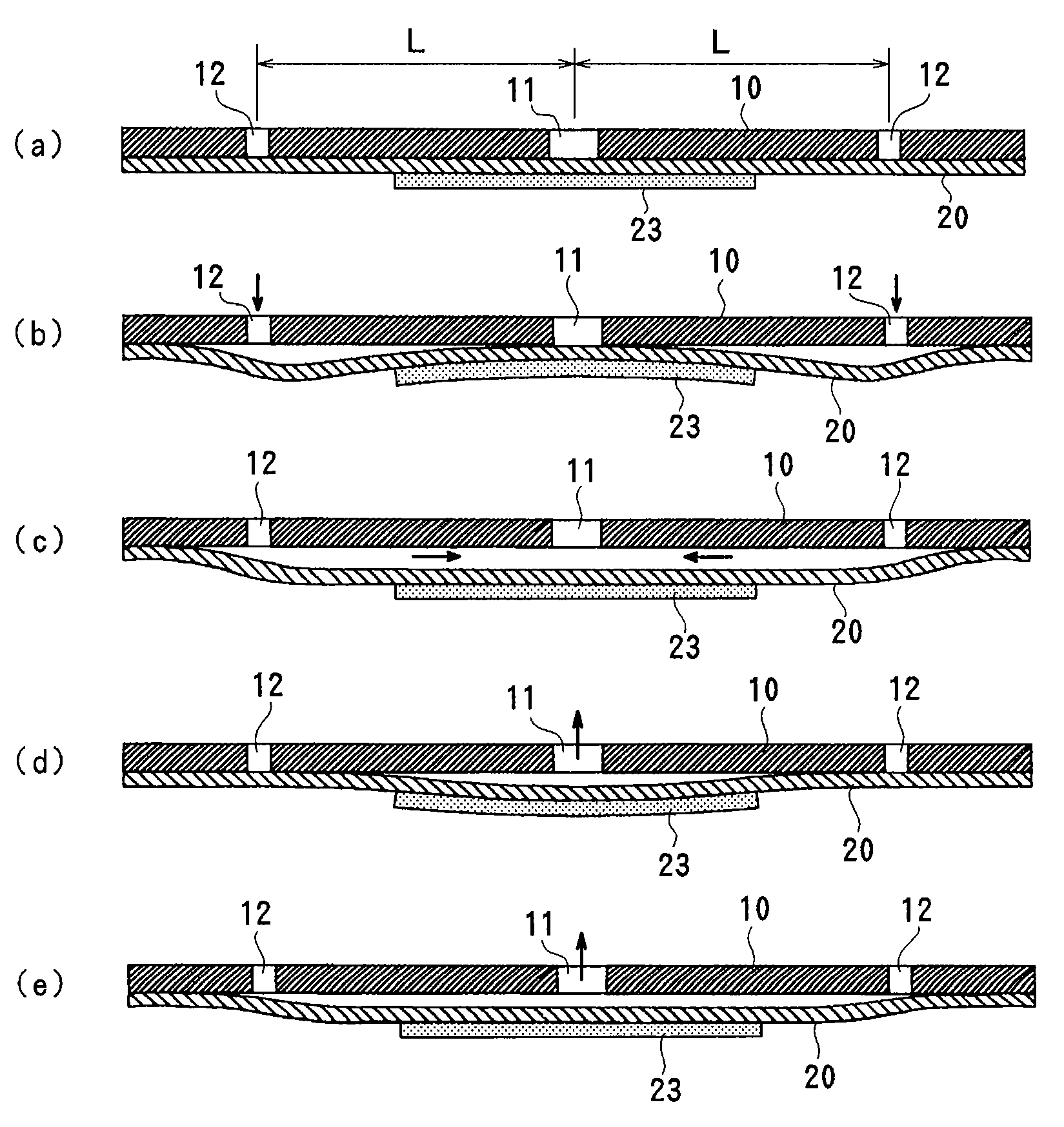
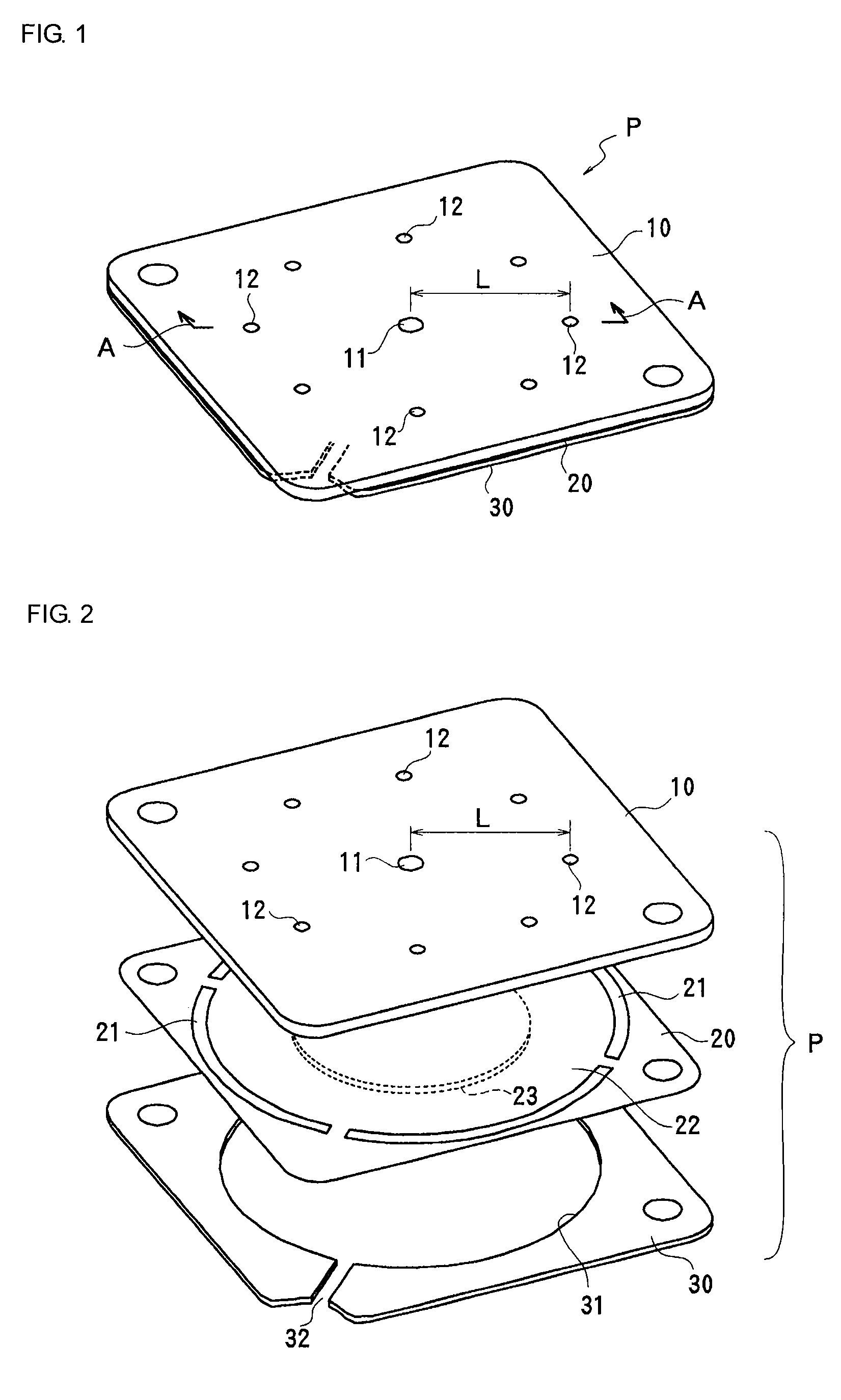
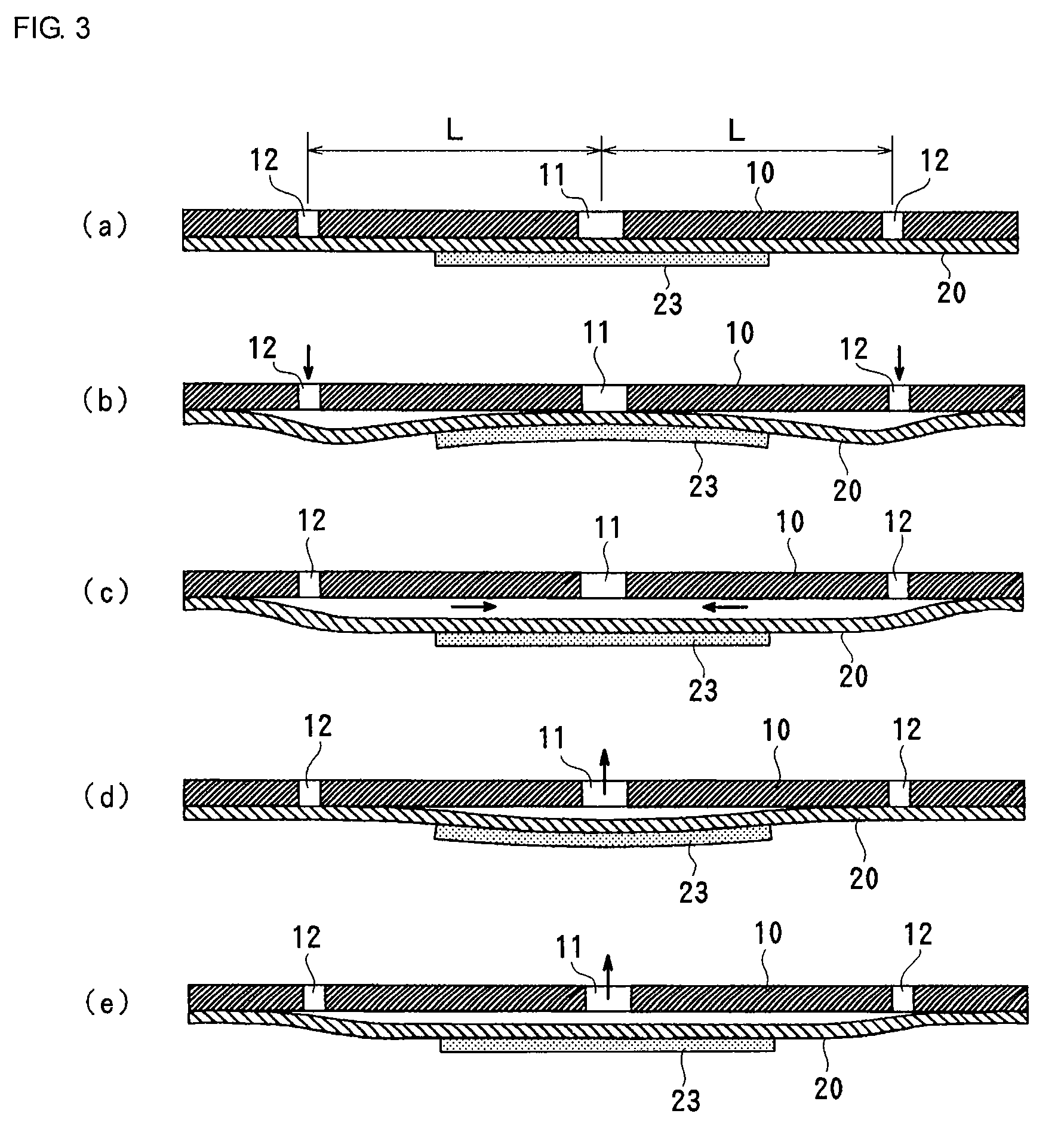
[0036]FIGS. 1 to 3 show a piezoelectric pump according to a first embodiment. FIG. 1 is a general perspective view of a piezoelectric pump according to the present invention, FIG. 2 is an exploded perspective view of the piezoelectric pump shown in FIG. 1, and FIG. 3 is a cross-sectional view, taken along line A-A in FIG. 1.

[0037]In this embodiment, a piezoelectric pump P has a structure in which a top plate 10 that forms a pump body, a diaphragm 20, and an annular presser plate 30 are stacked in order, and these stacked components are bonded together. The top plate 10 is shaped like a flat plate having rigidity. A first opening 11 is provided at the center of the top plate 10, and a plurality of second openings 12 are provided on the same circumference centered on the first opening 11. While eight second openings 12 are provided so as to ensure the flow rate herein, the number of second openings 12 can be arbitrarily set in accordance with the required flow rate.

[0038]The diaphragm...

second embodiment

[0053]FIG. 5 shows a pumping operation in a tertiary resonance mode according to a second embodiment of the present invention. The same components as those shown in FIG. 3 are denoted by the same reference numerals, and redundant descriptions thereof are omitted. While the second openings 12 are provided in the pump body 10 in the first embodiment, second openings 25 are provided in a diaphragm 20 in this embodiment. In this case, when driving is performed in a tertiary resonance mode, fluid can be drawn in from the second openings 25 on the back side of a piezoelectric pump and can be discharged from a first opening 11 on the front side. This structure is suitable for an air supply pump in a fuel cell or a cooling pump.

third embodiment

[0054]FIG. 6 shows a pumping operation in a tertiary resonance mode according to a third embodiment of the present invention. The same components as those shown in FIG. 3 are denoted by the same reference numerals, and redundant descriptions thereof are omitted. In this embodiment, a part of a pump body 10 extends outward from a diaphragm 20, and a second opening 16 shaped like a concave groove is provided on a lower side of an extending portion 15 so as to extend from an inner side of an outer peripheral portion to an outer side of the diaphragm 20. An inner edge of the second opening 16 is provided outside the outer periphery of a piezoelectric element 23 and inside a fixed outer peripheral portion of the diaphragm 20, and an outer edge thereof is open on the lower side from the extending portion 15. The second opening 16 does not always need to be shaped like a concave groove, and may be formed by a communicating hole that is open outside the piezoelectric element 23 and inside t...


PUM


Abstract

A piezoelectric pump having a first opening in a center portion of a pump body, and a second opening apart from the center. An outer peripheral portion of a metal diaphragm is fixed to the pump body, and a piezoelectric element having a size that covers the first opening and does not cover the second opening is bonded to a back center portion of the diaphragm. By applying a voltage near the resonance frequency to the piezoelectric element, a portion of the diaphragm opposing the first opening and a portion of the diaphragm opposing the second opening are bent in opposite directions so that fluid is drawn in from one of the first opening and the second opening and is discharged from the other opening. Such a piezoelectric pump can increase the discharging pressure, and can reliably discharge the fluid even under a condition where the pressure on the discharging side is high.

Description

CROSS REFERENCE TO RELATED APPLICATIONS[0001]The present application is a continuation of International Application No. PCT / JP2007 / 073555, filed Dec. 6, 2007, which claims priority to Japanese Patent Application No. JP2006-332692, filed Dec. 9, 2006, the entire contents of each of these applications being incorporated herein by reference in their entirety.FIELD OF THE INVENTION[0002]The present invention relates to piezoelectric pumps, and more particularly, to a piezoelectric pump using a diaphragm that is bent by a piezoelectric element.BACKGROUND OF THE INVENTION[0003]Piezoelectric pumps are used as cooling pumps in small electronic devices, such as notebook personal computers, and fuel transportation pumps in fuel cells. A piezoelectric pump is a pump using a diaphragm that is bent by the application of voltage to a piezoelectric element, and has advantages of a simple structure, a low profile structure, and low power consumption. In a piezoelectric pump using a piezoelectric el...

Claims


Application Information

Patent Timeline
Patent Type & Authority Applications(United States)
IPC IPC(8): F04B17/00
CPCF04B43/04F04B45/04F04B43/046Y02E60/50F04B2201/0806F05B2280/10F05B2260/407F05B2210/11F04B45/047F04B45/045F04B43/028F05B2260/60Y10S417/00
Inventor KAMITANI, GAKUSUNAGA, MIDORI
Owner MURATA MFG CO LTD
Why Eureka
Try Eureka