
Starting control device for vehicle and starting control method

a technology of starting control and starting clutch, which is applied in the direction of machines/engines, vehicle sub-unit features, transportation and packaging, etc., can solve the problems of lowering the starting performance and the hydraulic fluid inside the hydraulic circuit is extremely deteriorated, so as to shorten the time lag, reduce the transmission responsiveness of the starting clutch drive force, and secure the effect of starting performan

Active Publication Date: 2020-03-03
JATCO LTD
View PDF30 Cites 3 Cited by
  • Summary
  • Abstract
  • Description
  • Claims
  • Application Information

AI Technical Summary

Benefits of technology

The patent text describes a system that increases the oil pressure supplied to a starting clutch in a vehicle during braking and in advance of releasing the brakes. This improves the responsiveness of the drive force and ensures a smooth starting performance. The system also uses an electric motor to speed up the oil pump and reduce delays in starting the vehicle. This results in decreased fuel consumption and less deterioration of fuel economy.

Problems solved by technology

However, if both of the traveling drive source and the electric motor are sopped (a non-driven state), the first and the second oil pumps are stopped, and hydraulic fluid inside a hydraulic circuit is lowered caused by leaking.
However, when the vehicle starts in a case where, when the vehicle runs over a level difference and at the time of a vehicle start on a climbing load, the accelerator pedal is depressed while the brake pedal is still depressed, following which the brake pedal is released, if the oil pump is driven with the release of the brake pedal as a trigger, it is difficult to sufficiently secure transmission responsiveness of drive force in a start clutch, and a problem arises that starting performance extremely deteriorates.

Method used


Image

  • Starting control device for vehicle and starting control method
  • Starting control device for vehicle and starting control method
  • Starting control device for vehicle and starting control method

Examples


embodiment

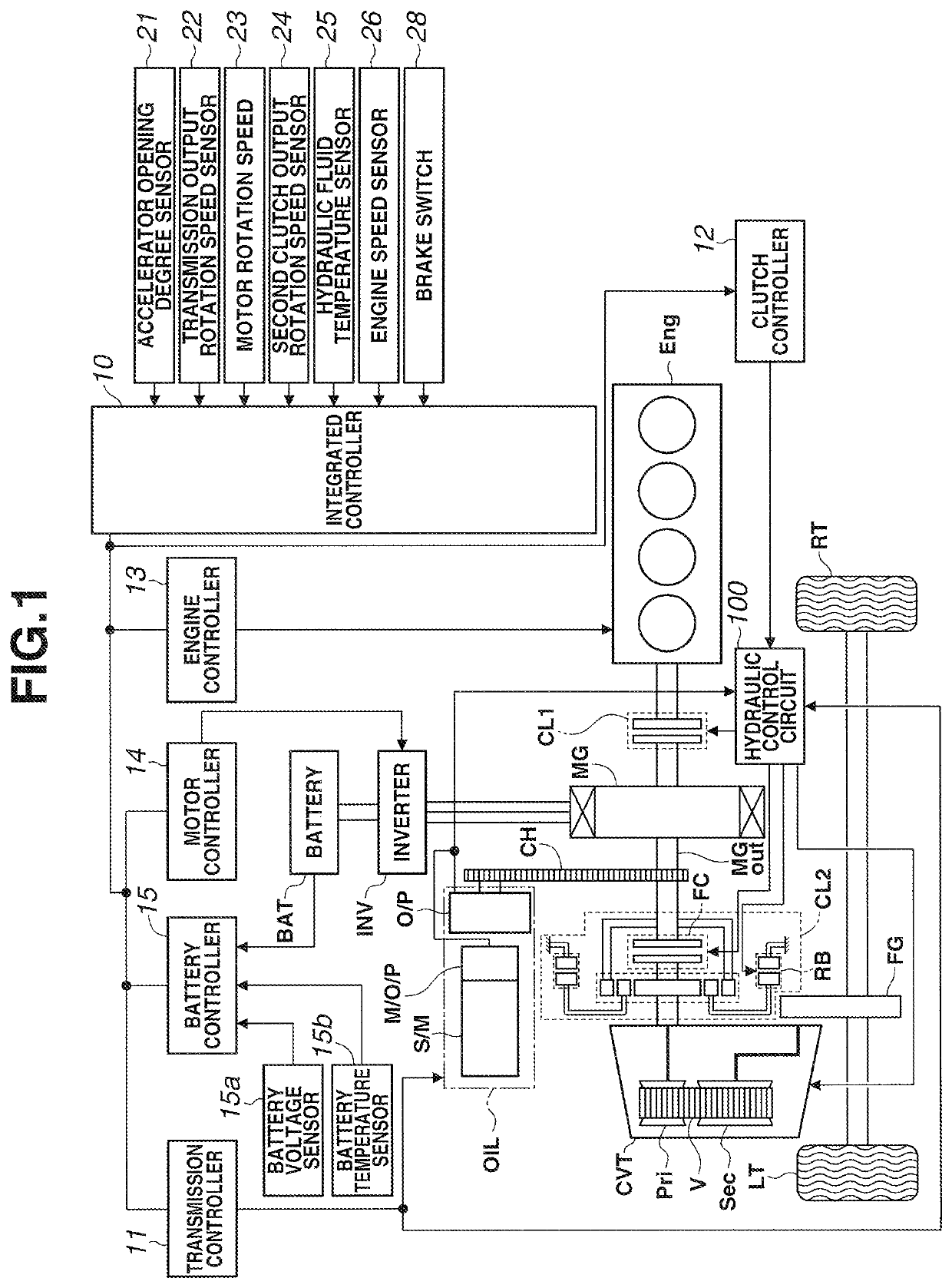
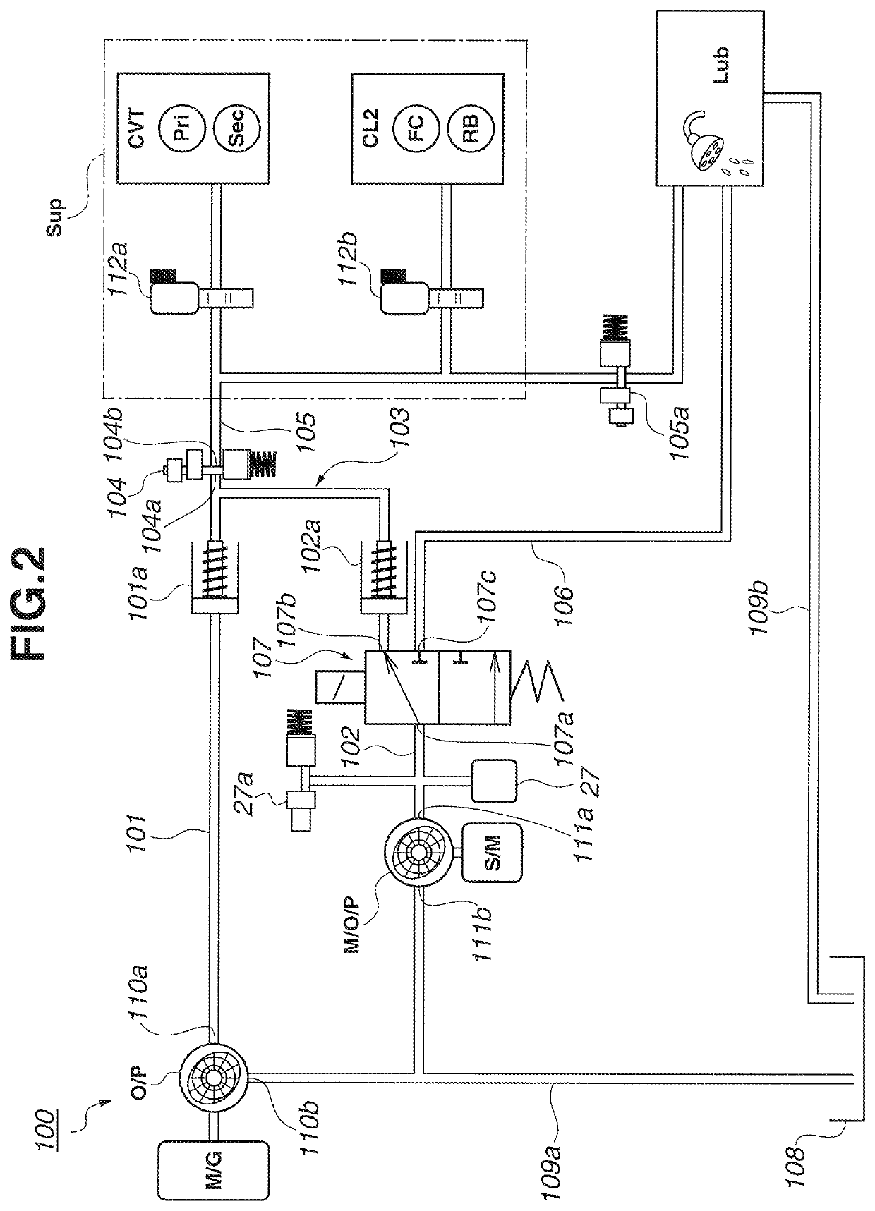
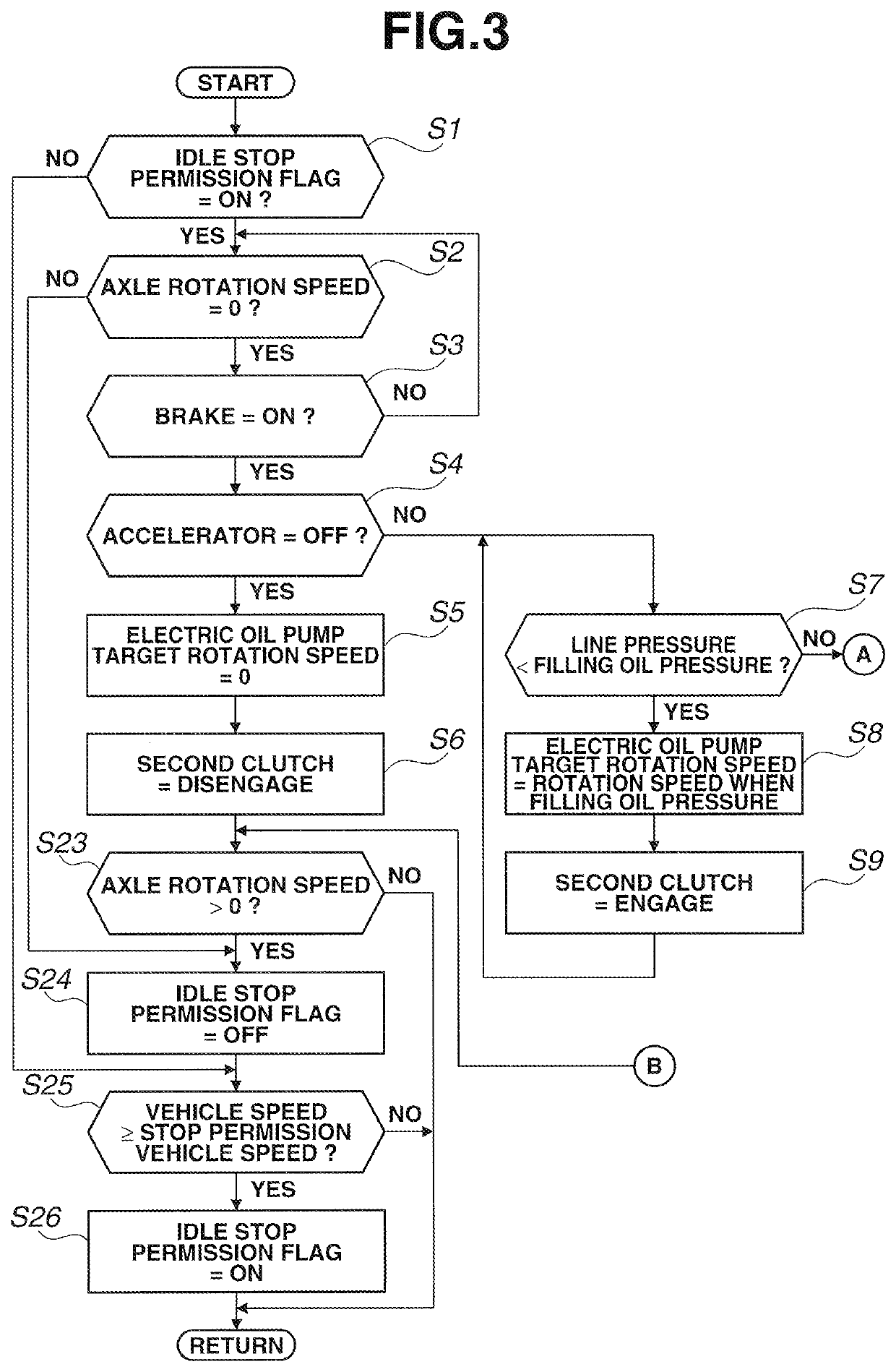
[0025]First, the configuration of the starting control device for the vehicle of the embodiment will be explained by dividing it into “entire system configuration of hybrid vehicle”, “detail configuration of hydraulic control circuit” and “control processing configuration at time of starting of vehicle”.

[0026][Entire System Configuration of Hybrid Vehicle]

[0027]FIG. 1 is the entire schematic system diagram showing a hybrid vehicle (one example of vehicles) in which a control device of an embodiment has been applied. In the following, based on FIG. 1, the entire system configuration of the hybrid vehicle of the embodiment will be explained.

[0028]The starting control device for the vehicle of the embodiment has been applied to the hybrid vehicle shown in FIG. 1. The drive system of this hybrid vehicle is provided with an engine Eng, a first clutch CL1, a motor / generator MG (motor for traveling), a second clutch CL2 (starting clutch), a continuously variable transmission CVT, a final g...


PUM


Abstract

A vehicle is provided with a mechanical oil pump (O / P) that is driven by a motor / generator (MG), an electric oil pump (M / O / P) that is driven by a sub-motor (S / M) and a second clutch (CL2) that transmits the drive force of the motor / generator (MG) to left and right drive wheels (LT, RT). When an accelerator pedal is depressed while a brake pedal is still depressed, an integrated controller (10) drives the electric oil pump (M / O / P) before the brake pedal is released, and oil pressure supplied to the second clutch (CL2) is increased.

Description

TECHNICAL FIELD[0001]The present invention relates to a starting control device for a vehicle in which a first oil pump that is driven by a traveling drive source and a second oil pump that is driven by an electric motor are provided.BACKGROUND TECHNOLOGY[0002]A related art vehicle has been known. As to the related art vehicle, a first oil pump that is driven by a traveling drive source and a second oil pump that is driven by an electric motor are provided, and when discharge pressure from the first oil pump is insufficient caused by a vehicle stop, the second oil pump is driven to suppress lowing of oil pressure (for example, see a patent document 1).[0003]It is preferable that the traveling drive source and the electric motor are stopped to improve fuel economy in a state in which a brake pedal has been depressed. However, if both of the traveling drive source and the electric motor are sopped (a non-driven state), the first and the second oil pumps are stopped, and hydraulic flui...

Claims


Application Information

Patent Timeline
Patent Type & Authority Patents(United States)
IPC IPC(8): B60W20/40F16H59/54F16D25/00F16H59/18F16D48/02B60K6/387B60L50/16F16H61/00B60K6/48B60W20/19B60W10/08B60W20/00B60W10/30B60W10/02B60W10/06F02D29/04B60K6/543
CPCF16H61/0031B60W20/40B60W10/30B60K6/387B60W20/19B60W10/06B60L50/16F02D29/04B60W20/00B60K6/48F16D48/02B60W10/02B60W10/08B60K6/543B60W2540/10Y10S903/918Y10S903/914F16H59/18B60W2710/021B60Y2200/92F16H2312/14B60Y2400/72B60W2540/12F16D25/00F16H59/54F16H61/02F16H63/50
Inventor KATAKURA, SHUSAKUSHIMIZU, YUTAKAKOIKE, TOMOYUKIINUTA, YUKIYOSHIYOSHIOKA, YOUKO
Owner JATCO LTD
Learn More