Gas sensor

A gas sensor and sensor element technology, applied in the direction of instruments, scientific instruments, measuring devices, etc., can solve the problems of sensor element damage, large thermal shock, sensor element application, etc., and achieve the effect of increasing temperature

Active Publication Date: 2014-12-24
DENSO CORP
View PDF8 Cites 4 Cited by
  • Summary
  • Abstract
  • Description
  • Claims
  • Application Information

AI Technical Summary

Problems solved by technology

Therefore, due to the adhesion of condensed water, a large thermal shock is applied to the sensor element, which may cause damage to the sensor element.

Method used


Image

  • Gas sensor
  • Gas sensor
  • Gas sensor

Examples


Embodiment 1

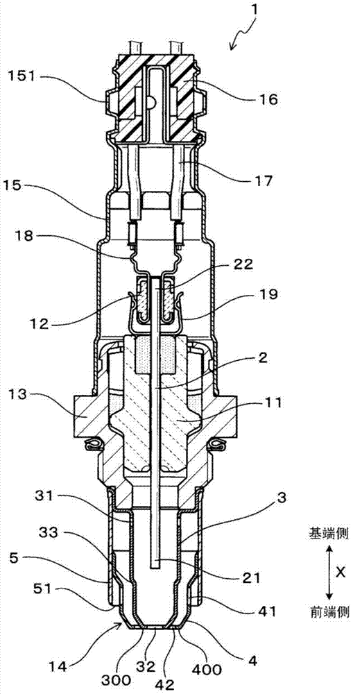
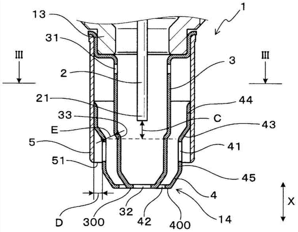
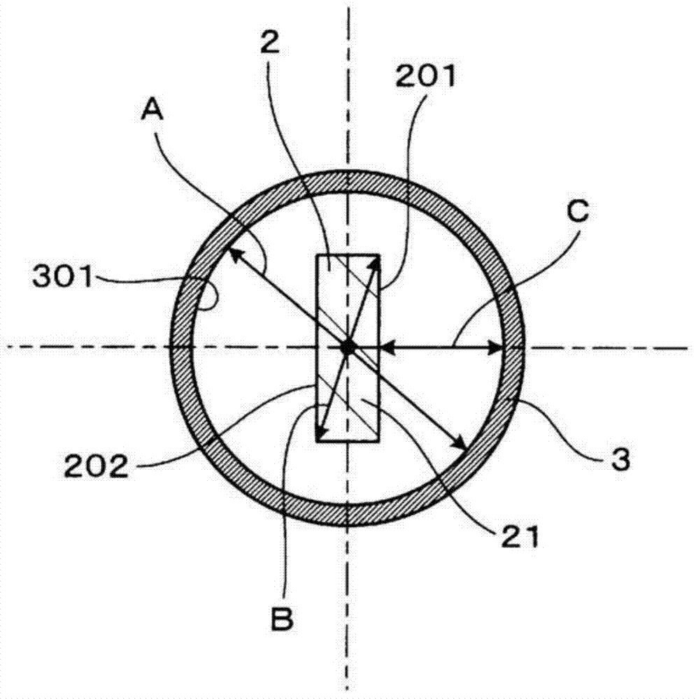
[0072] The gas sensor 1 in this example is as Figure 1 ~ Figure 3 It includes a sensor element 2 for detecting the concentration of a specific component in a gas to be measured (namely, a gas to be measured), a case 13 through which the sensor element 2 is inserted, and an element cover 14 disposed on the front end side of the case 13 .

[0073] The element cover 14 has an inner cover 3 arranged to cover the front end portion 21 of the sensor element 2 , and an outer cover 4 arranged outside the inner cover 3 . The outer cover 4 has an outer introduction hole 41 through which the gas to be measured is introduced, and an outer discharge hole 42 provided on the front end side than the outer introduction hole 41 . The inner cap 3 has an inner introduction hole 31 provided on the proximal side than the outer introduction hole 41 to introduce the gas to be measured, and an inner discharge hole 32 provided on the distal side than the inner introduction hole 31 .

[0074] As shown ...

Embodiment 2

[0113] Such as Image 6 As shown, this example is an example in which the structures of the outer cover 4 and the protective cover 5 are changed.

[0114] In this example, if the Image 6 As shown, the outer cover 4 is formed so as to extend toward the base end side than the protective cover 5 , and is fixed to the front end side of the housing 13 together with the inner cover 3 . In addition, the protective cover 5 is fixed to the fixing portion 46 on the side wall of the outer cover 4 that is closer to the proximal side than the outer diameter-reduced portion 43 .

[0115] Other basic structures and effects are the same as in Example 1.

Embodiment 3

[0117] Such as Figure 7 As shown, this example is an example in which the structure of the protective cover 5 is changed.

[0118] In this example, if the Figure 7 As shown, a protruding portion 52 protruding radially inward is provided at the front end portion of the protective cover 5 . Furthermore, the protective cover 5 has a front end side opening 51 that opens toward the front end side between the protruding portion 52 and the outer cover 4 .

[0119] Other basic structures and effects are the same as in Embodiment 2.


PUM


Abstract

A gas sensor (1) is provided with a sensor element (2), a housing (13), and an element cover (14). The element cover (14) has an inner cover (3) and an outer cover (4). The outer cover (4) has an outer introducing port (41) and an outer discharge port (42). The inner cover (3) has an inner introducing port (31) and an inner discharge port (32). On the diameter direction outer side of the outer cover (4), a protection cover (5) having the leading end side thereof opened is disposed to cover the outer introducing port (41), and a predetermined interval is provided between the outer cover (4) and the protection cover (5). The inner cover (3) is provided with a diameter reducing step portion (33) having the diameter thereof reduced toward the leading end side. The diameter reducing step portion (33) is positioned between the outer introducing port (41) and the inner introducing port (31) in the axis direction X. When the inner diameter of the inner cover (3) is represented by A, and the diameter direction maximum length of the leading end portion (21) of the sensor element (2) is represented by B, the relationship of A/B<=2.1 is satisfied.

Description

technical field [0001] The present invention relates to a gas sensor for detecting the concentration of a specific component in a gas to be measured (ie, gas to be measured). Background technique [0002] Conventionally, a gas sensor is known which is installed in an exhaust system of an internal combustion engine of an automobile or the like to detect concentrations of specific components such as oxygen and nitrogen oxides in exhaust gas which is a gas to be measured. [0003] Specifically, the gas sensor includes, for example, a sensor element that detects the concentration of a specific component in a gas to be measured, a case through which the sensor element is inserted, and an element cover disposed on the front end side of the case. [0004] In addition, the above-mentioned gas sensor is configured such that the surface of the sensor element is in contact with the exhaust gas which is the gas to be measured. However, when the internal combustion engine is started at ...

Claims


Application Information

Patent Timeline
Patent Type & Authority Applications(China)
IPC IPC(8): G01N27/409
CPCG01N27/4077
Inventor 中村正毅森胁淳二鲤江和俊
Owner DENSO CORP
Why Eureka
Try Eureka