

Compressor
A technology for compressors and compression mechanisms, applied in the field of compressors, can solve the problems of poor responsiveness, large discharge resistance, and overcompression loss, and achieves the reduction of responsiveness, the increase of flow velocity, and the suppression of overcompression loss. Effect
- Summary
- Abstract
- Description
- Claims
- Application Information
AI Technical Summary
Problems solved by technology
Method used
Image

Examples
no. 1 approach
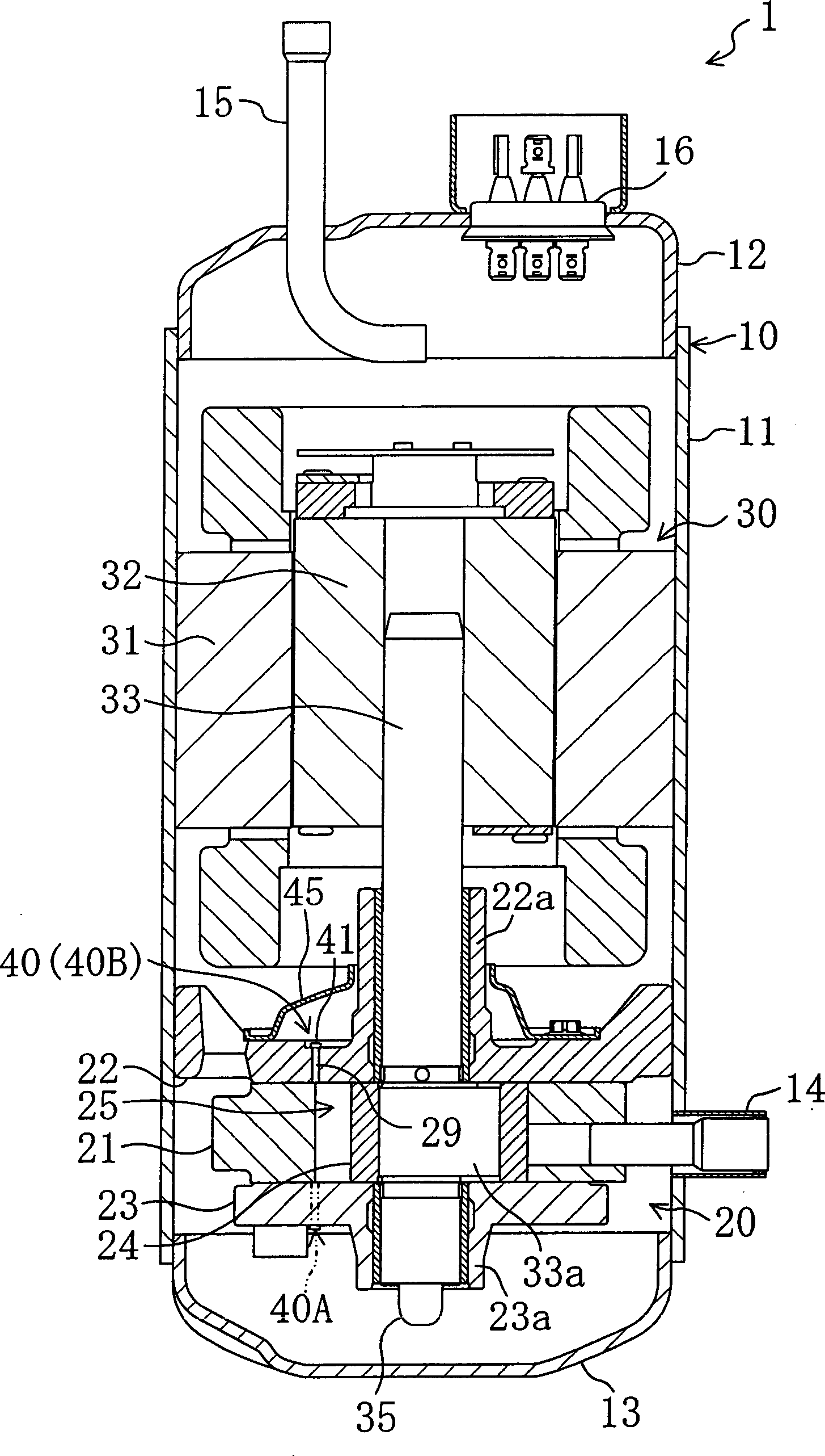
[0052] Hereinafter, a first embodiment of the present invention will be described in detail with reference to the drawings.
[0053] This embodiment relates to a rotary piston type compressor (1). like figure 1 As shown, the compressor (1) accommodates a compression mechanism (20) and a motor (drive mechanism) (30) that drives the compression mechanism (20) in the casing (10), and is a fully enclosed structure. The compressor (1) drives a compression mechanism (20) by an electric motor (30), sucks in refrigerant, compresses it, and then discharges it so that it circulates in a refrigerant circuit.
[0054] The casing (10) is composed of a cylindrical casing body (11) constituting the peripheral wall of the casing (10) and cover plates (12, 13) fixed on the upper and lower ends of the casing body (11). Moreover, both the compression mechanism (20) and the motor (30) are fixed on the casing body (11) of the casing (10), and the compression mechanism (20) is located below the m...
no. 2 approach
[0083] The second embodiment of the present invention is an example in which the structure of the discharge valve mechanism (40) of the first embodiment is modified.
[0084] The discharge valve mechanism (40) is controlled by figure 1 Shown by phantom lines in , the first valve mechanism (40A) disposed on the rear end cap (23) side and the second valve mechanism (40B) disposed on the front end cap (22) side constitute.
[0085] In this second embodiment, if Image 6 As shown, the first discharge port (29a) is formed on the rear end cover (23), and the first valve mechanism (40A) is configured to open and close the first discharge port (29a) by using the first valve plate (41A) as a reed valve . and, if Figure 5 As shown, the second discharge port (29b) is formed in the front end cover (22), and the second valve mechanism (40B) is configured to open and close the second discharge port (29b) by the second valve plate (41B) as a poppet valve. The poppet valve (41B) is forme...
no. 3 approach
[0091] The third embodiment of the present invention is an example in which one valve plate has the functions of a reed valve and a poppet valve.
[0092] The discharge valve mechanism (40) is provided on the front end cover (22) side as in the first embodiment. In this discharge valve mechanism (40), the first discharge port (29a) is a circular hole with a constant inner diameter, and the second discharge port (29b) is formed as a cone whose inner diameter gradually increases from the inside to the outside of the compression chamber (25). hole. The first discharge port (29a) is formed at the front end side of the valve plate (43), and the second discharge port (29b) is formed at the base end side thereof.
[0093] The part of the valve plate (43) corresponding to the first discharge port (29a) is formed in a flat plate shape, and the part corresponding to the second discharge port (29b) is formed in a frustoconical shape to fit the second discharge port (29b). That is, the ...
PUM
 Abstract
Description
Claims
Application Information