Plate heat exchanger device and a heat exchanger plate

a heat exchanger and heat exchanger plate technology, which is applied in indirect heat exchangers, lighting and heating apparatuses, laminated elements, etc., can solve the problems of difficult to provide one unit for the heat exchanger part and the separation part to reasonable costs, and the need for a large number of components and connecting conduits, so as to prevent the liquid from being remixed. , the effect of efficient liquid separation

Inactive Publication Date: 2005-09-29
ALFA LAVAL CORP AB
View PDF12 Cites 29 Cited by
  • Summary
  • Abstract
  • Description
  • Claims
  • Application Information

AI Technical Summary

Benefits of technology

[0005] The object of the present invention is to provide an efficient separation of liquid from a substantially gaseous medium and to prevent remixing of the liquid with the gaseous medium. In particu

Problems solved by technology

Such devices with a separate heat exchanger and a separate liquid separator have the disadvantage that a significant number of components and connecting conduits are required.
However, it h

Method used


Image

  • Plate heat exchanger device and a heat exchanger plate
  • Plate heat exchanger device and a heat exchanger plate
  • Plate heat exchanger device and a heat exchanger plate

Examples


first embodiment

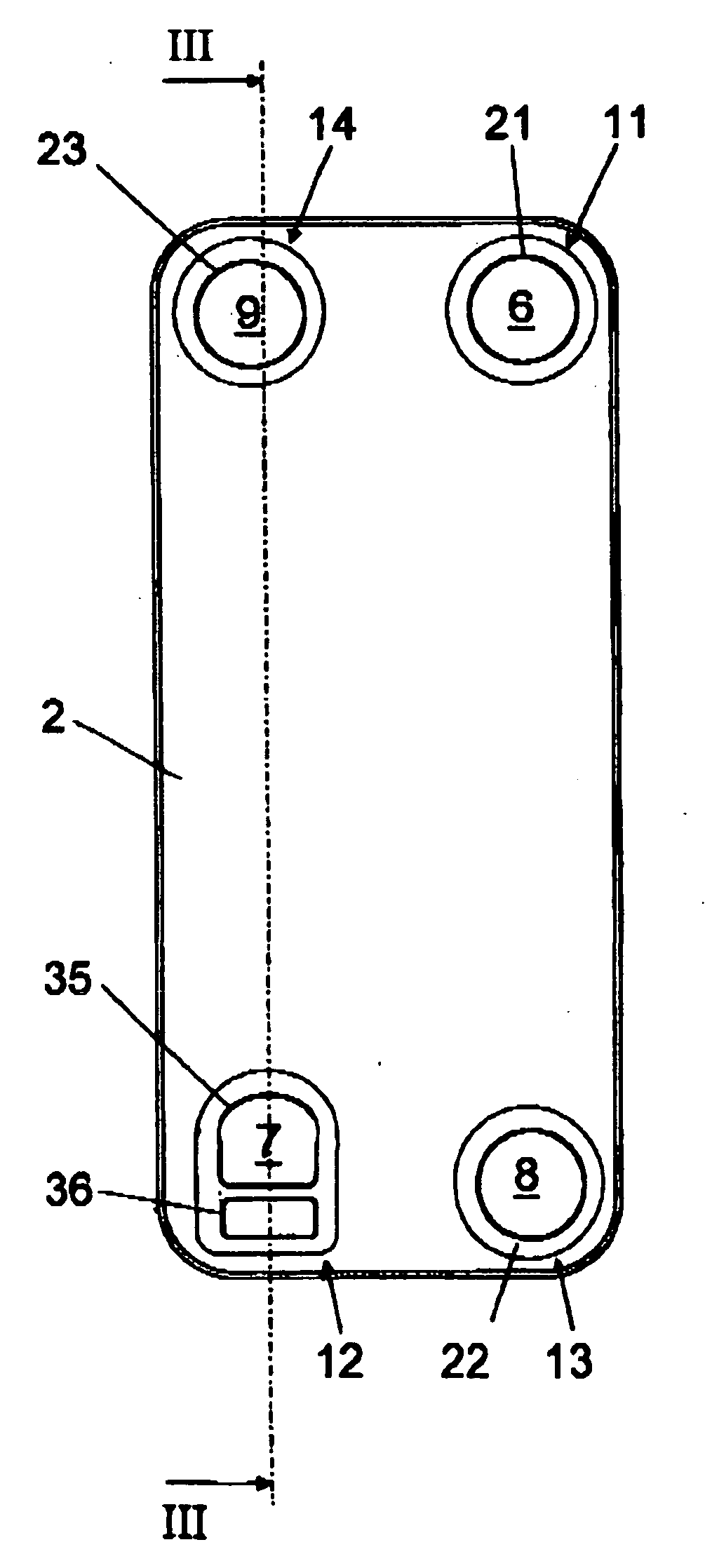
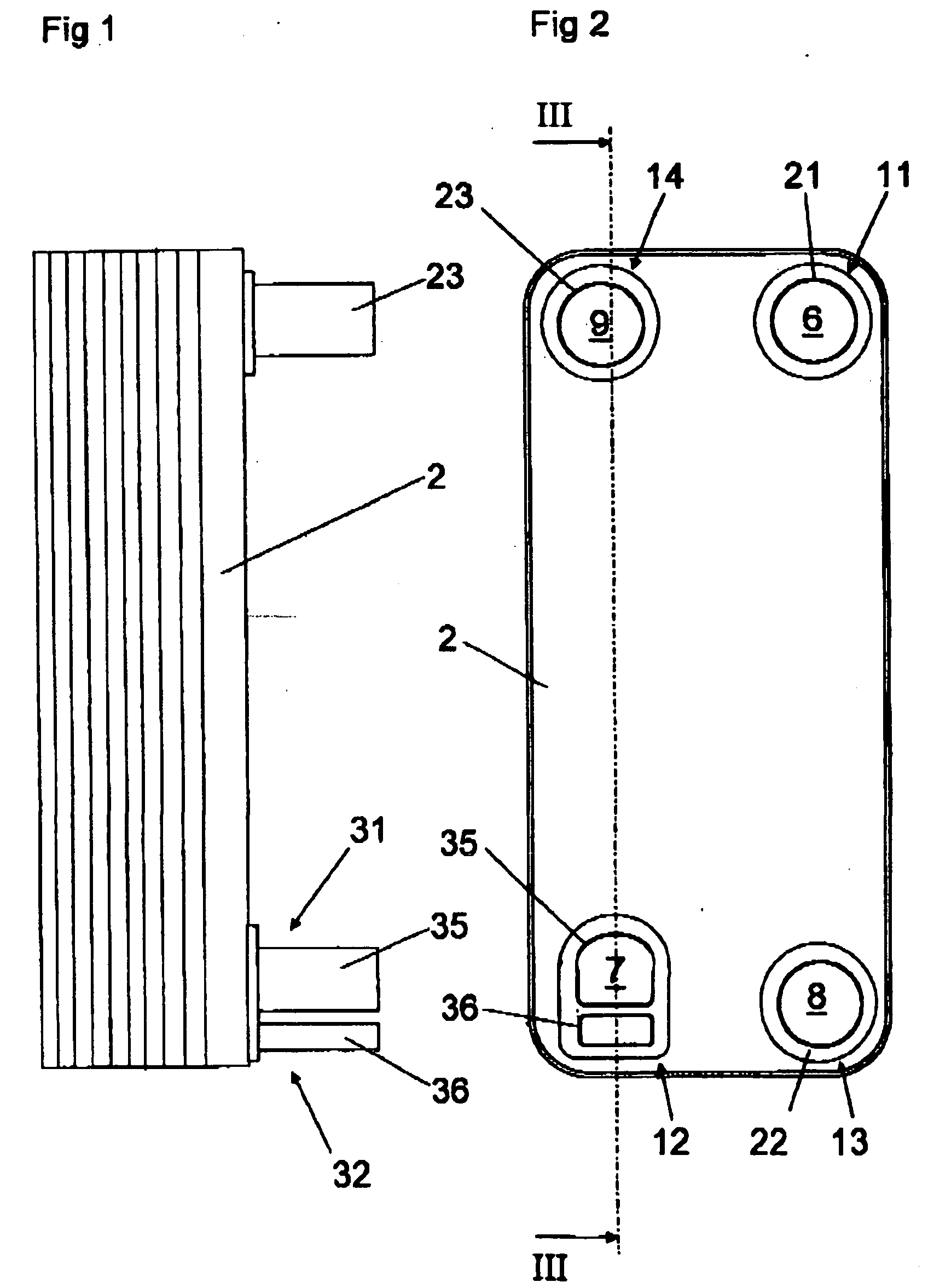
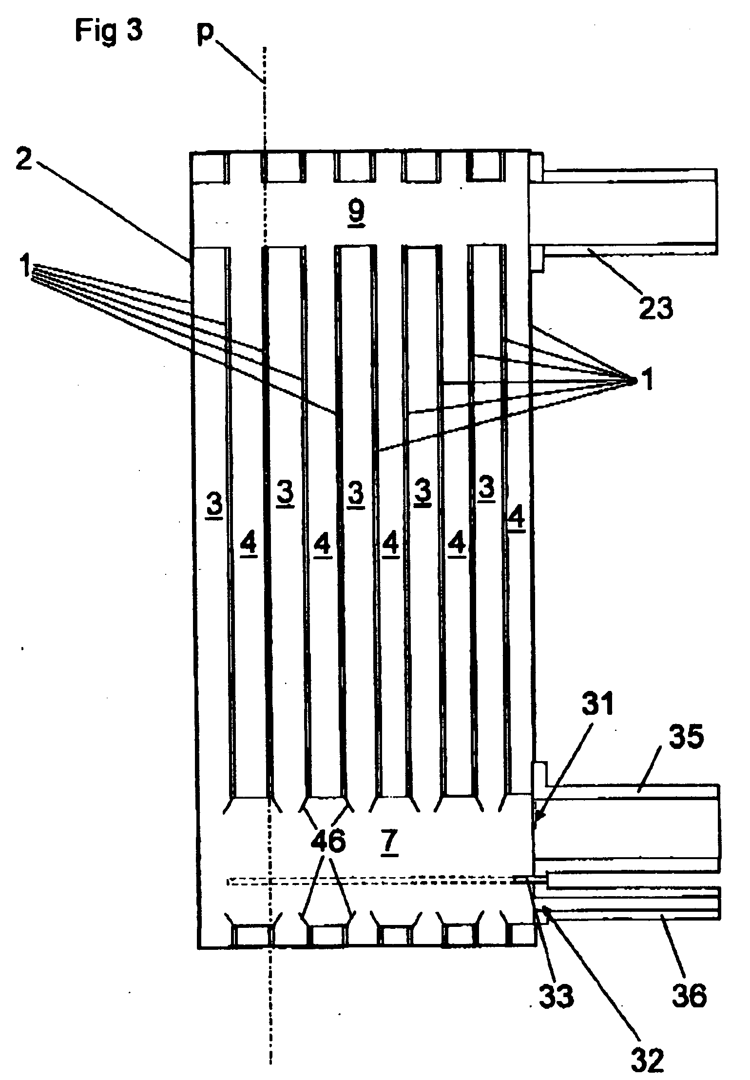
[0036] FIGS. 1 to 3 discloses a plate heat exchanger according to the invention. The plate heat exchanger Includes a number of heat exchanger plates 1, which form a plate package 2 and which each Includes a main extension plane p, see FIG. 3. The heat exchanger plates 1 are pressed to such a shape that when they are provided beside each other to said plate package 2, a plate interspace is formed between each pair of plates 1. The plate interspaces, which completely or partly also may be formed by distance members, for instance gaskets, provided between the plates, are arranged to form first passages 3 for a first medium and second passages 4 for a second medium. The first passages 3 are separated from the second passages 4. Furthermore, the first passages 3 and the second passages 4 are arranged beside each other in an alternating order, i.e. substantially each first passage 3 is surrounded by two second passages 4.

[0037] The plate package 2 includes in the embodiment disclosed heat...

fourth embodiment

[0053] The further plate interspaces 3a, 3b, disclosed in the fourth embodiment, are intended to convey the first medium. The plate interspaces 3a, which substantially consists of every second one of the further plate interspaces 3a, 3b, form a part of the first inlet 11. The first medium is thus conveyed via the conduit pipe 21 through the plate interspaces 3a to the first inlet port channel 6. The plate interspaces 3b, which substantially consist of every second one of the further plate interspaces 3a, 3b, form a part of the first outlet 12. The gaseous part of the first medium is thus conveyed from the first outlet port channel 7, via a corresponding port channel 7a of the plate package 2a through the plate interspaces 3b to the gas outlet 31 and the gas discharge conduit 35. The corresponding port channel 7a have the same size and the same shape as the first outlet port channel 7. Furthermore, the corresponding port channel 7a has the same position as the first outlet port chann...


PUM


Abstract

The invention refers to a device, including a plate package (2) of heat exchanger plates (1) which are provided beside each other to form a plate interspace between adjacent plates, and a heat exchanger plate. The plate interspaces form in an alternating order first passages (3) for a first medium and second passages (4) for a second medium for cooling of the first medium. Each heat exchanger plate has at least two portholes forming a first inlet port channel and a first outlet port channel (7), which extend through the plate package to a first inlet and a first outlet, respectively, for the first medium to and from the first passages (3). The first outlet forms a gas outlet (31) for discharge of a gas of the first medium and a liquid outlet (32) for discharge of liquid of the first medium. The liquid outlet (32) is separated from the gas outlet (31) for permitting separate discharge of the liquid and gas.

Description

THE BACKGROUND OF THE INVENTION AND PRIOR ART [0001] The present invention refers to a plate heat exchanger device, including a plate package formed by a number of heat exchanger plates, which are arranged beside each other In such a manner that a plate interspace is formed between adjacent plates, which plate interspaces form first passages for a first medium and second passages for a second medium, that is arranged to cool the first medium, wherein the first passages and the second passages are arranged beside each other in the plate package in an alternating order, wherein the first passages are separated from the second passages, and wherein substantially each heat exchanger plate has at least two portholes forming a first inlet port channel and a second outlet port channel, which extend through the plate package to a first inlet and a first outlet, respectively, for the first medium to and from the first passages. [0002] The invention also refers to a heat exchanger plate for a...

Claims


Application Information

Patent Timeline
IPC IPC(8): F28F3/08F28D9/00F28F3/04
CPCF28D9/005F28F3/04F25B39/022F28F3/046F28F2265/18
Inventor EKELUND, ROLFCHRISTENSEN, ROLFLINDHOLM, INGVAR
Owner ALFA LAVAL CORP AB
Why Eureka
Try Eureka