Surface treatment apparatus

a surface treatment and apparatus technology, applied in the field of apparatus, can solve the problems of difficult to treat a large area of a surface, low performance of a surface treatment, and high manufacturing cost, and achieve the effect of efficient treatment and miniaturization of exhaust configuration

Inactive Publication Date: 2000-07-11
SEIKO EPSON CORP
View PDF54 Cites 91 Cited by
  • Summary
  • Abstract
  • Description
  • Claims
  • Application Information

AI Technical Summary

Benefits of technology

In the case of this apparatus of the present invention, the gas is supplied to the discharge region from a downstream side of the second electrode in the direction of the movement of the workpiece and is exhausted at an upstream side of the second electrode. Thus, air can be prevented from being mixed in the discharge region. Moreover, the electric discharge can be stabilized. Furthermore, even if impurities are deposited onto the surface of the workpiece at an upstream side of the discharge region, the redeposited substances can be removed in the discharge region as a result of the movement of the workpiece. Additionally, the gas used in the discharge processing can be exhausted from a vicinity of the discharge region, so that the exhausted gas can be efficiently treated without being emitted into the air. Moreover, the exhaust configuration can be miniaturized.

Problems solved by technology

Conventional plasma surface treatment methods have problems in that generally, special equipment and facilities, such as a vacuum chamber, are required to cause a plasma discharge in a reduced pressure environment, the performance of a surface treatment is low and it is difficult to treat a surface of a large area.
As a result, the manufacturing cost becomes high.
Thus, there are concerns that cracks and warpage are caused by local stress caused therein and thermal stress, owing to the high temperature of a plasma discharge; and that if a crack or warpage occurs in the porous dielectric 8, the desired function of uniformly distributing the gas over the discharge region cannot be performed; conversely, if the output of the power supply is suppressed in order to prevent the temperature of the discharge plasma from becoming excessively high, a sufficient discharge is not obtained, the performance of a surface treatment is lowered and thus the treatment rate becomes reduced or the surface treatment is not sufficiently achieved; and that further, if a crack is produced in the dielectric 8, the function of preventing an occurrence of an abnormal discharge, which is the essential function of the dielectric 8, is impaired.
Thus, when a certain gap between the dielectric 8 and the workpiece to be treated is not maintained owing to a mounting error or the like of the apparatus, there are concerns that a deviation or deflection of a gas flow is caused, that an irregularity or nonuniformity is caused in the distribution of the gas in the discharge region 11 and that the entire workpiece cannot be treated uniformly.
Further, there are additional concerns that organic substances and the like removed from the workpiece can be redeposited thereon during ejection from the discharge region and that thus, the workpiece can become contaminated and the maintenance of the apparatus can be difficult.
In contrast, in the case of using a carbon material or SUS base material, such a material reacts with gases such as O.sub.2 and CF.sub.4, so that oxidization and corrosion are liable to occur.
Therefore, there is a concern that a detached material from the electrode can contaminate the surface of the workpiece and the interior of the apparatus.
Especially, in the case that the workpiece to be treated is a silicon wafer, metal contamination by, for example, Fe can be a problem.
As a result, the operating cost is increased.
Eventually, the cost of the apparatus becomes high.
Further, in the case of the conventional surface treatment apparatus of FIG. 13, it is difficult to cause an electric discharge uniformly in the longitudinal direction of the electrode under near atmospheric pressure even if the width of the discharge generating portion is made to be uniform, which is different from the case of a vacuum discharge.
Moreover, because of the problem of an abnormal discharge, there is a limit to the power for causing an electric discharge.
Consequently, especially, in the case of treatment of a large area, it is difficult to achieve a uniform treatment.
Moreover, the realization of high-speed treatment cannot be expected.
Thus, there are concerns that the distribution of the gas ejected in the longitudinal direct ion of the electrode becomes nonuniform and that uniform surface treatment cannot be achieved and consequently, the enhancement of the treatment performance cannot be accomplished.
This conventional apparatus, however, has a problem in that when the flow rate of helium is increased correspondingly to the dispersion of the gas, the treatment cost is increased considerably.
Further, there are concerns that because air is mixed in the discharge region when the gas is dispersed, that the discharge will become unstable, or the organic substances or the like, which have been removed, will react with impurities contained in the air and become redeposited onto the surface of the workpiece.
Furthermore, in the case of such a surface treatment apparatus, regardless of the electrode configuration, even when the dielectric for protecting the electrode is provided therein, there are concerns that abnormal discharges such as an arc discharge are caused and thus, that the workpiece and a stage on which the workpiece is placed, will be damaged.
Consequently, such an apparatus has problems in that the output thereof is limited, that therefore, the treatment performance cannot be sufficiently enhanced and neither high-speed treatment nor reduction in cost can be achieved.

Method used


Image

  • Surface treatment apparatus
  • Surface treatment apparatus
  • Surface treatment apparatus

Examples


first embodiment

(First Embodiment)

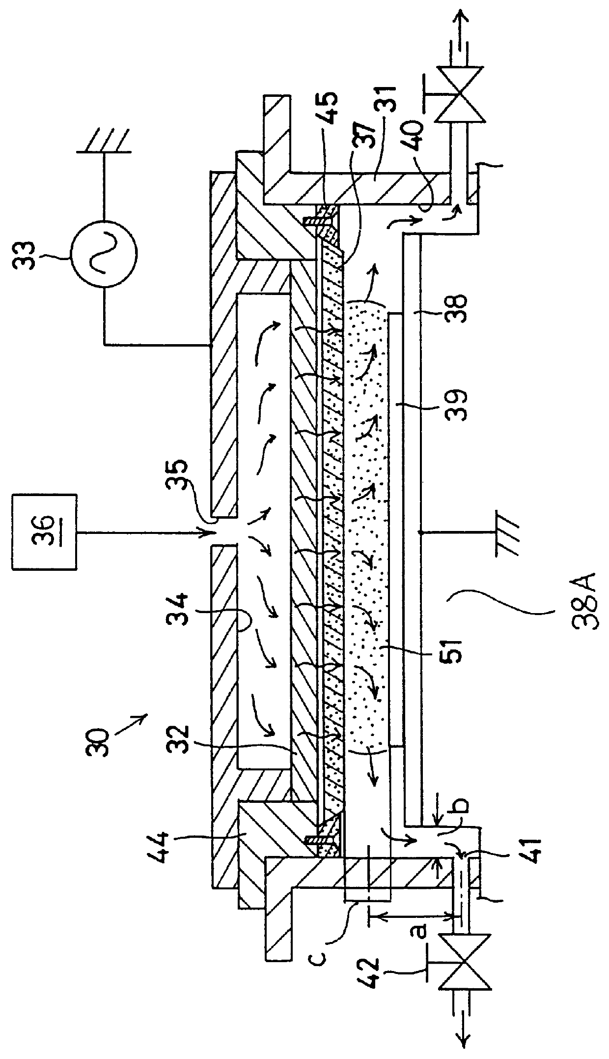
FIG. 1 illustrates the configuration of a preferred embodiment of the present invention, namely, a surface treatment apparatus of the opposed-face type embodying the present invention. The surface treatment apparatus 30 has a disk-like electrode 32 placed horizontally in a round housing 31. The electrode 32 is constituted of a porous element made of, for example, an aluminum material and is connected to an alternating current power supply 33. A chamber 34 defined by the upper part of the electrode 32 is connected to an external gas supply 36 through a gas inlet 35. A disk-like dielectric 37 made of a porous material such as a ceramic material, for example, alumina (Al.sub.2 O.sub.3) or the like is placed under the bottom surface of the electrode 32.

Under the dielectric 37, a workpiece, namely, a workpiece 39 such as a wafer, on which a surface treatment is performed, is placed in such a manner that a gap having a constant width of about 1 to 2 mm or so is formed be...

second embodiment

(Second Embodiment)

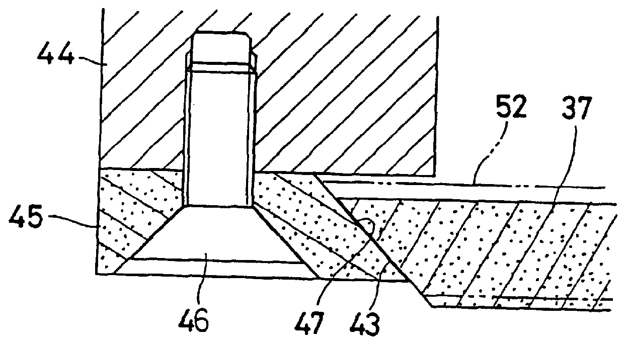
FIG. 3 illustrates the configuration of a second embodiment of the present invention, namely, another surface treatment apparatus of the face type embodying the present invention. Although a surface treatment apparatus 52 of this embodiment has a configuration which is nearly similar to that of the surface treatment apparatus 30 of FIG. 1, many gas inlets 53 are opened in the housing 31 at uniform intervals in the circumferential direction in such a way that the discharge gas is uniformly supplied into a discharge region 51, which is a gap, whose width is 1 to 2 mm, formed between the dielectric 37 and the work 39 from the surroundings thereof in various directions. Flow rate regulation means 54 are provided at the gas inlets 53, respectively. Thereby, even in the case where a gap is not uniformly formed between the dielectric 37 and the work 39 owing to a mounting error or the like of the surface treatment apparatus 52, the gas can be fed to the discharge region ...

third embodiment

(Third Embodiment)

FIG. 4 illustrates the configuration of a third embodiment of the present invention, namely, a surface treatment apparatus of the opposed-face type embodying the present invention. In the case of this embodiment, an auxiliary grounded electrode 57 for abnormal discharge processing is provided on the top surface of a stage (the first electrode) 38 in such a way as to protrude from the stage 38 at a position which is shifted outward from the work 39 and is under the electrode 32. The gap between the tip end of the auxiliary grounded electrode 57 and the electrode (the second electrode) 32 can be suitably adjusted by changing the length of the projected part thereof from the stage 38 by using screws or the like. Namely, the gap is adjusted to a suitable value in such a way that the impedance between the faces of the electrode 32 and the auxiliary grounded electrode 57, which are opposed to each other, becomes locally lower than the plasma impedance corresponding to th...


PUM

PropertyMeasurementUnit
constant widthaaaaaaaaaa
widthaaaaaaaaaa
pressureaaaaaaaaaa

Abstract

PCT No. PCT/JP96/00935 Sec. 371 Date Dec. 6, 1996 Sec. 102(e) Date Dec. 6, 1996 PCT Filed Apr. 5, 1996 PCT Pub. No. WO96/31997 PCT Pub. Date Oct. 10, 1996In a surface treatment apparatus (30) of the face type, a porous dielectric (37) is supported by the outer periphery portion of the supporting member (45) under the bottom surface of a porous electrode (32). The dielectric can be supported by the supporting member to permit the thermal expansion deformation of the dielectric by forming an upward inclined-face (47) and a downward inclined-face (43) on the supporting member (45) and the dielectric (37), respectively. Further, a discharge gas can be supplied uniformly to a discharge region (51) through the electrode (32) and the dielectric (37), both of which are porous. Many gas exhaust ports (41), by which the flow rate of the gas can be regulated, are provided around the discharge region (51). Thus, the gas is uniformly exhausted around the discharge region (51). Especially, if the gap between the dielectric (37) and a work (39) depends on mounting accuracy or the like and varies with location, the gas can be exhausted uniformly around the discharge region (51).

Description

[TECHNICAL FIELD]The present invention relates to an apparatus for treating a surface of a workpiece, which is to be treated, by utilizing a plasma. For example, in semiconductor fabrication, the present invention is used for etching and ashing a surface of a workpiece, or for performing surface modification on a workpiece, and for performing thin film deposition.[BACKGROUND ART]Heretofore, in various fields, there have been utilized techniques for variously treating a surface of a workpiece by using a plasma in this way. Conventional plasma surface treatment methods have problems in that generally, special equipment and facilities, such as a vacuum chamber, are required to cause a plasma discharge in a reduced pressure environment, the performance of a surface treatment is low and it is difficult to treat a surface of a large area. As a result, the manufacturing cost becomes high. Thus, recently, there have been proposed surface treatment techniques as described in, for example, th...

Claims


Application Information

Patent Timeline
Patent Type & Authority Patents(United States)
IPC IPC(8): H01J37/32
CPCH01J37/32834
Inventor MIYASHITA, TAKESHIMIYAKAWA, TAKUYAAOKI, YASUTUGUKUBOTA, ISAOKURASHINA, OSAMUASANO, YASUHIKOODA, YOSHIOMORI, YOSHIAKI
Owner SEIKO EPSON CORP
Why Eureka
Try Eureka