Brush-seal and matrix for regenerative heat exchanger, and method of adjusting same

a heat exchanger and matrix technology, applied in the field of heat exchangers, can solve the problems of increasing seal wear, clogging of porous matrix, reducing the efficiency of the regenerator, etc., and achieve the effect of preventing fluid flow mixing

Inactive Publication Date: 2009-01-01
WILSON SOLARPOWER CORP
View PDF3 Cites 87 Cited by
  • Summary
  • Abstract
  • Description
  • Claims
  • Application Information

AI Technical Summary

Benefits of technology

[0004]The present invention solves the aforementioned problems by providing a regenerative heat exchanger including a brush-seal configuration to prevent mixing of fluid flows. The regenerative heat exchanger includes a regenerator matrix, and at least two conduits, each conduit having a matrix end abutting a face of the regenerator matrix. At least two conduits carry at least two fluid flows which pass through the regenerator matrix. The regenerative heat exchanger includes a plurality of brush-seals. Each brush-seal is located at a matrix end of each conduit without contacting the matrix, thereby sealing around a periphery of each conduit to prevent mixing of fluid flows.

Problems solved by technology

With non-contact seals (which do not contact the matrix face), it is a major challenge to properly adjust a gap between the matrix face and the non-contact seal minimizing leakage to maximize efficiency of the heat exchanger.
Use of contact seals, however, causes increased seal wear and also reduces efficiency of the regenerator due to the increased function between the contact seal and the matrix that must be overcome in the rotation of the matrix.
Additionally, rubbing of the contact seals on the regenerator matrix can over time produce solid material (either from the matrix or the seals) which will contaminate the flow and might lead to clogging in a porous matrix.

Method used


Image

  • Brush-seal and matrix for regenerative heat exchanger, and method of adjusting same
  • Brush-seal and matrix for regenerative heat exchanger, and method of adjusting same
  • Brush-seal and matrix for regenerative heat exchanger, and method of adjusting same

Examples


Embodiment Construction

[0010]The detailed description explains embodiments of the invention, together with advantages and features, by way of example with reference to the drawings.

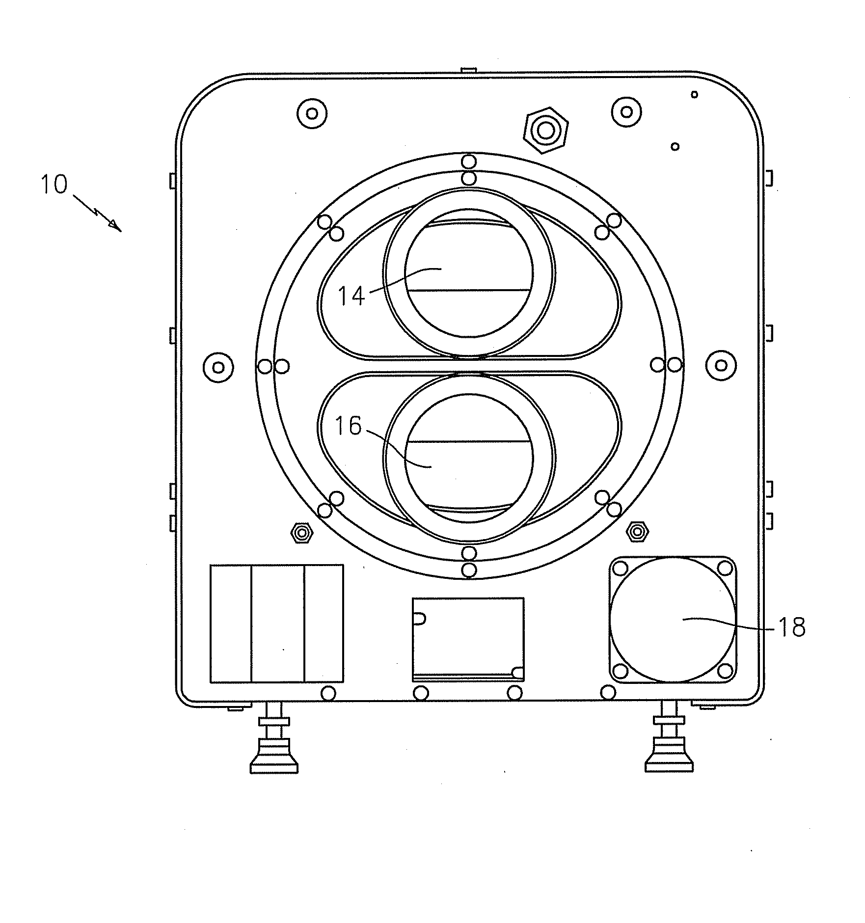
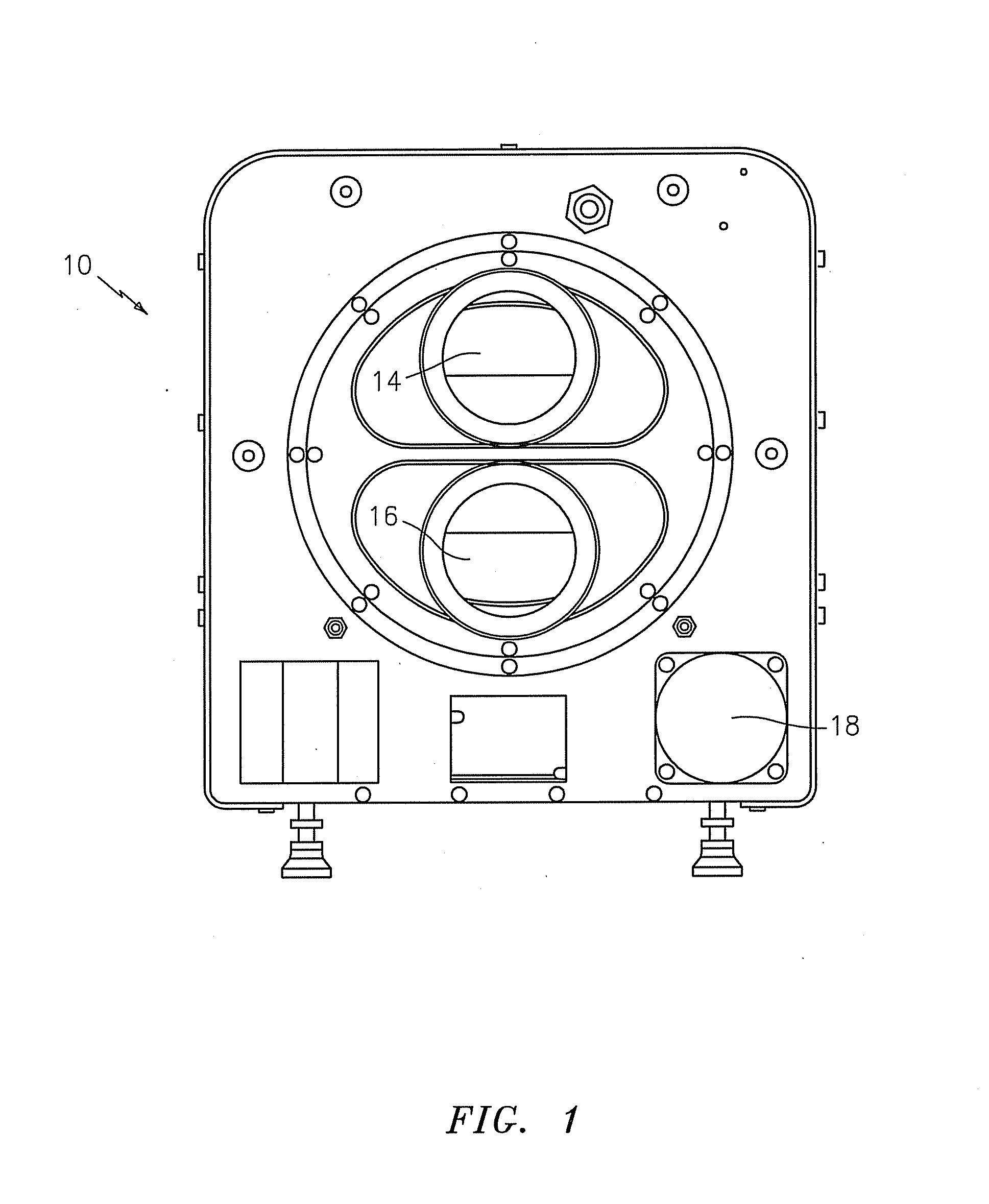
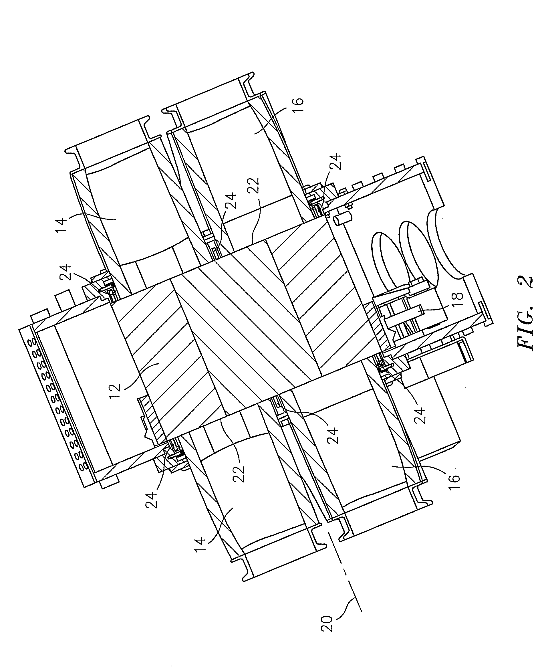
[0011]Shown in FIG. 1 is an embodiment of a regenerative heat exchanger (regenerator) 10. Referring now to FIG. 2, the regenerator 10 includes a regenerator matrix 12. The matrix 12 generally comprises a body having a plurality of internal passageways (not shown) oriented in all axial direction, and may be formed of a low-thermal-conductivity and high-heat-capacity material, for example, a ceramic material. In some embodiments, the matrix 12 may include an abradable coating layer (not shown) to protect the matrix 12 material from wear. The matrix 12 in some embodiments is cylindrical in shape, but other shapes are contemplated within the scope of this invention. The matrix 12 is disposed across two or more fluid streams. Each fluid stream is carried in a conduit. In this embodiment, a cold fluid stream is carried in a first con...


PUM


Abstract

Disclosed is a regenerative heat exchanger including a brush-seal configuration to prevent mixing of fluid flows. The regenerative heat exchanger includes a regenerator, and at least two conduits, each conduit having a matrix end abutting a face of the regenerator matrix. The at least two conduits carrying at least two fluid flows, the fluid flows which pass through the regenerator matrix. The regenerative heat exchanger includes a plurality of brush-seals, each brush-seal located at a matrix end of each conduit without contacting the matrix, thereby sealing around a periphery of each conduit to prevent mixing of fluid flows. Also disclosed is a method for establishing a minimal gap between a regenerator matrix of a regenerative heat exchanger and a plurality of brush-seals.

Description

BACKGROUND OF THE INVENTION[0001]This invention generally relates to heat exchangers. In particular, the present invention relates to seals for rotary regenerative heat exchangers.[0002]A regenerative heat exchanger (regenerator) uses a heat transfer matrix which is rotated through a hot and a cold stream consecutively to transfer heat from the former to the latter. The device call also be used to transfer mass between two fluids differing in concentration in a targeted constituent and the exchange (be it mass and / or heat) can involve any number of flows greater than one.[0003]Each of the hot and cold flows is typically carried to and from the matrix by a conduit. The flows enter and exit the matrix through a face of the matrix, and a configuration of seals is located between the conduits and the rotating matrix face to prevent leakage of the flows from the conduits into the environment or from one flow into another. Two types of seals are generally used, non-contact seals or contac...

Claims


Application Information

Patent Timeline
Patent Type & Authority Applications(United States)
IPC IPC(8): F23L15/02
CPCF28D19/047F23L15/02Y02E20/34
Inventor WILSON, DAVID GORDONBALLOU, JON M.WARD, KELLY
Owner WILSON SOLARPOWER CORP
Why Eureka
Try Eureka