Electrostatic inkjet head

a technology of inkjet head and electric motor, which is applied in the field of printing head, can solve the problems of reducing the durability of equipment, reducing the accuracy of inkjet printing, and damage to the resistance heater, and achieves the effect of increasing the ink discharge pressure and large displacemen

Inactive Publication Date: 2006-09-07
SAMSUNG ELECTRO MECHANICS CO LTD
View PDF1 Cites 2 Cited by
  • Summary
  • Abstract
  • Description
  • Claims
  • Application Information

AI Technical Summary

Benefits of technology

[0015] The present invention provides an electrostatic inkjet head which allows a great electrostatic force regardless of the distance between the diaphragm and the electrode, whereby a large displacement may be created of the diaphragm and the ink discharge pressure may be increased.

Problems solved by technology

The bubble jet type comprises a resistance heater, where the repeated rapid heating and cooling of the operation means cause damage to the resistance heater and lower the durability of the equipment.
The piezoelectric type requires minute processing of the piezoelectric element, so that its manufacture is time-consuming and complicated, and entails a risk of decreased precision.
Therefore, the distance between the two structural plates becomes the maximum value of the displacement by which the diaphragm may be deformed, so that there is a limit to how great the displacement can be made for the conventional electrostatic inkjet head.
In addition, closer distances between the two structural plates lead to a greater number of difficulties in the manufacturing process, with the occurrence of various problems such as insufficient pressure in discharging ink, etc.
In said invention, however, pressure is transferred to the diaphragm through the outer frame connected to the rotor, to result in a complicated structure and increases in manufacturing time and costs.

Method used


Image

  • Electrostatic inkjet head
  • Electrostatic inkjet head
  • Electrostatic inkjet head

Examples


Embodiment Construction

[0035] Hereinafter, preferred embodiments of the electrostatic inkjet head and manufacturing method thereof according to the invention will be described in more detail with reference to the accompanying drawings. In the description with reference to the accompanying drawings, those components are rendered the same reference number that are the same or are in correspondence regardless of the figure number, and redundant explanations are omitted. Also, the basic principles will first be described before discussing the preferred embodiments of the invention.

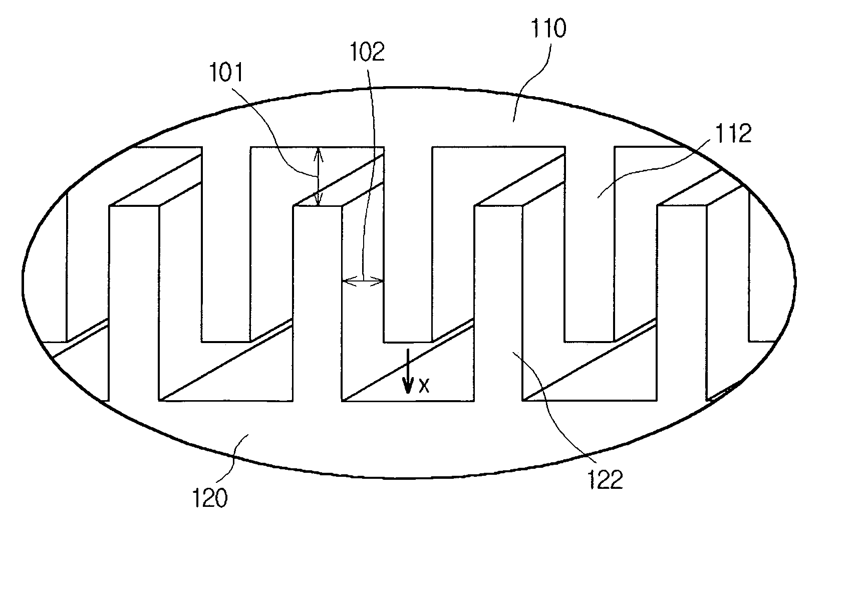
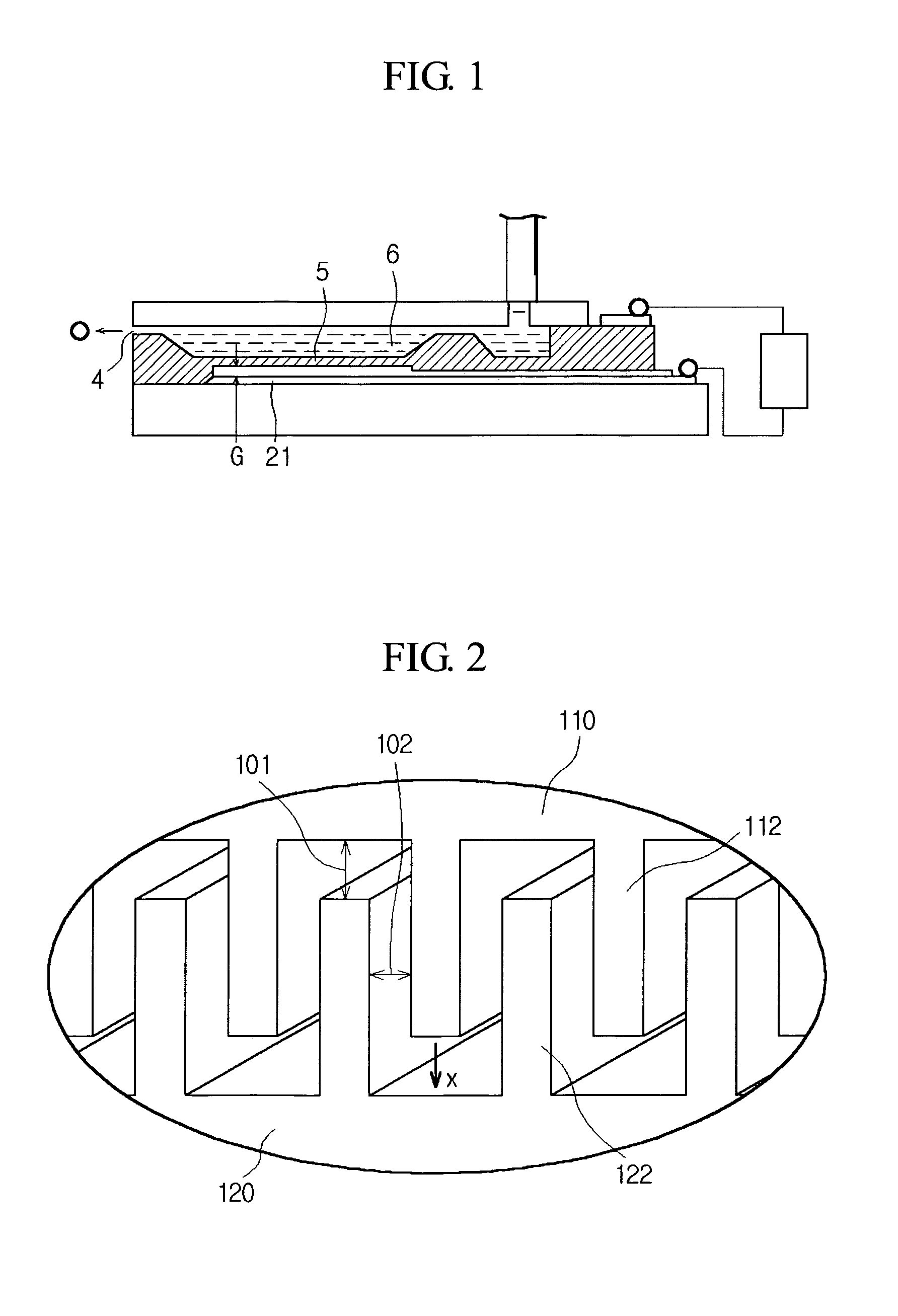
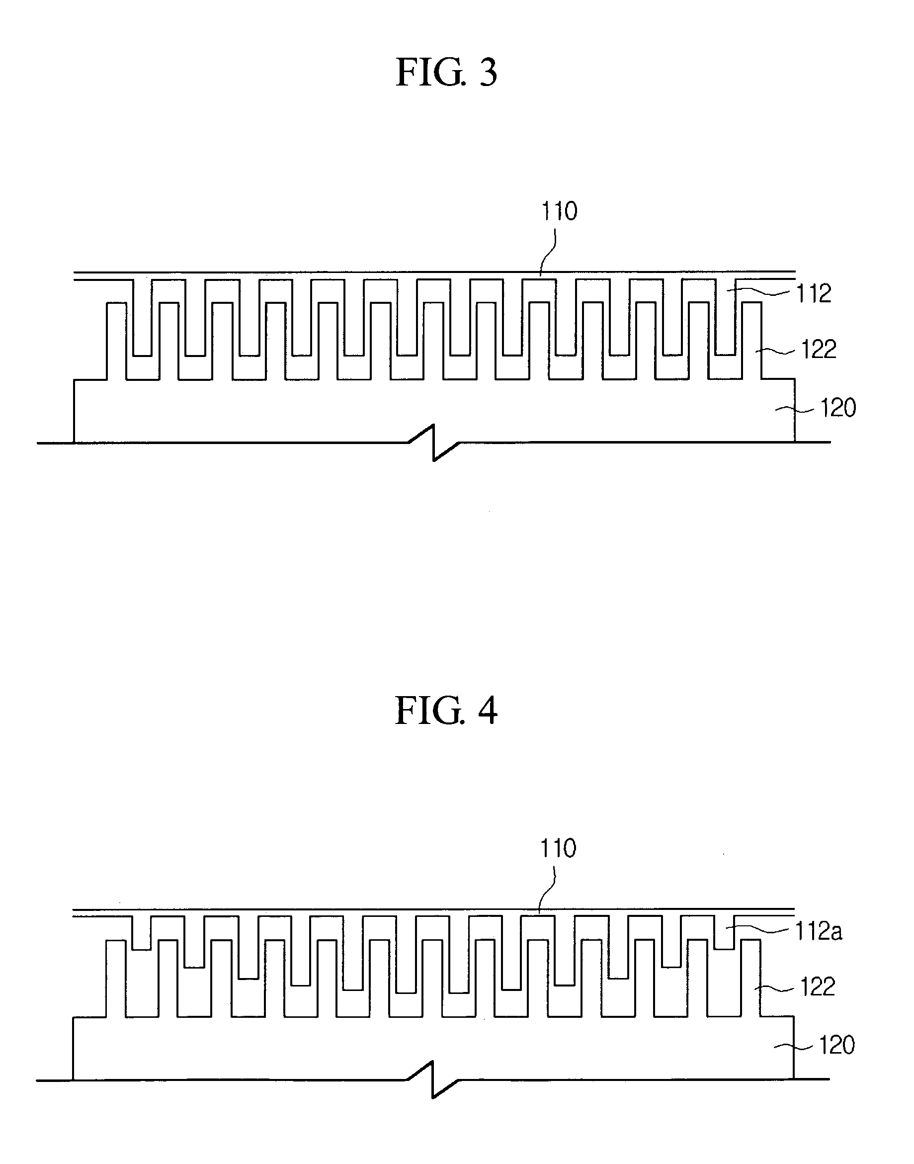
[0036]FIG. 2 is a magnified view of an electrostatic inkjet head according to a preferred embodiment of the invention, and FIG. 3 is a cross-sectional view of a diaphragm and an electrode of an electrostatic inkjet head according to a first preferred embodiment of the invention. In FIGS. 2 and 3 are illustrated a diaphragm 110, first protrusions 112, an electrode 120, and second protrusions 122.

[0037] This embodiment provides an e...


PUM


Abstract

An electrostatic inkjet head and manufacturing method thereof are disclosed. With an electrostatic inkjet head, comprising a deformable diaphragm comprised in a face of an ink chamber, one or more first protrusions protruding from a face of the diaphragm, a structurally fixed electrode facing the diaphragm, and one or more second protrusions protruding from a face of the electrode towards the diaphragm, wherein the first protrusions and the second protrusions are arranged alternately so that their sides are in proximity with each other, the electrostatic force may be increased regardless of the distance between the diaphragm and the electrode, whereby the maximum displacement is increased by which the diaphragm may be deformed, as well as the ink discharge pressure, to allow the discharge of high-viscosity ink.

Description

CROSS-REFERENCE TO RELATED APPLICATIONS [0001] This application claims the benefit of Korean Patent Application No. 2005-18505 filed with the Korea Intellectual Property Office on Mar. 7, 2005, the disclosure of which is incorporated herein by reference. BACKGROUND OF THE INVENTION [0002] 1. Field of the Invention [0003] The present invention relates to a printer head, and in particular, to an electrostatic inkjet head and manufacturing method thereof. [0004] 2. Description of the Related Art [0005] Typical operation types for inkjet printers include the bubble jet type and the piezoelectric type. The bubble jet type comprises a resistance heater, where the repeated rapid heating and cooling of the operation means cause damage to the resistance heater and lower the durability of the equipment. The piezoelectric type requires minute processing of the piezoelectric element, so that its manufacture is time-consuming and complicated, and entails a risk of decreased precision. [0006] To ...

Claims


Application Information

Patent Timeline
Patent Type & Authority Applications(United States)
IPC IPC(8): B41J2/06
CPCB41J2/14314B41J2/16B41J2/1623B41J2/1628B41J2/1631B41J2/164B41J2/14233
Inventor LIM, JAE-SEONGOH, SUNG-ILKIM, YOUNG-JAE
Owner SAMSUNG ELECTRO MECHANICS CO LTD
Why Eureka
Try Eureka