Conference recording device, conference recording method, and design method and storage media storing programs
- Summary
- Abstract
- Description
- Claims
- Application Information
AI Technical Summary
Benefits of technology
Problems solved by technology
Method used
Image
Examples
first embodiment
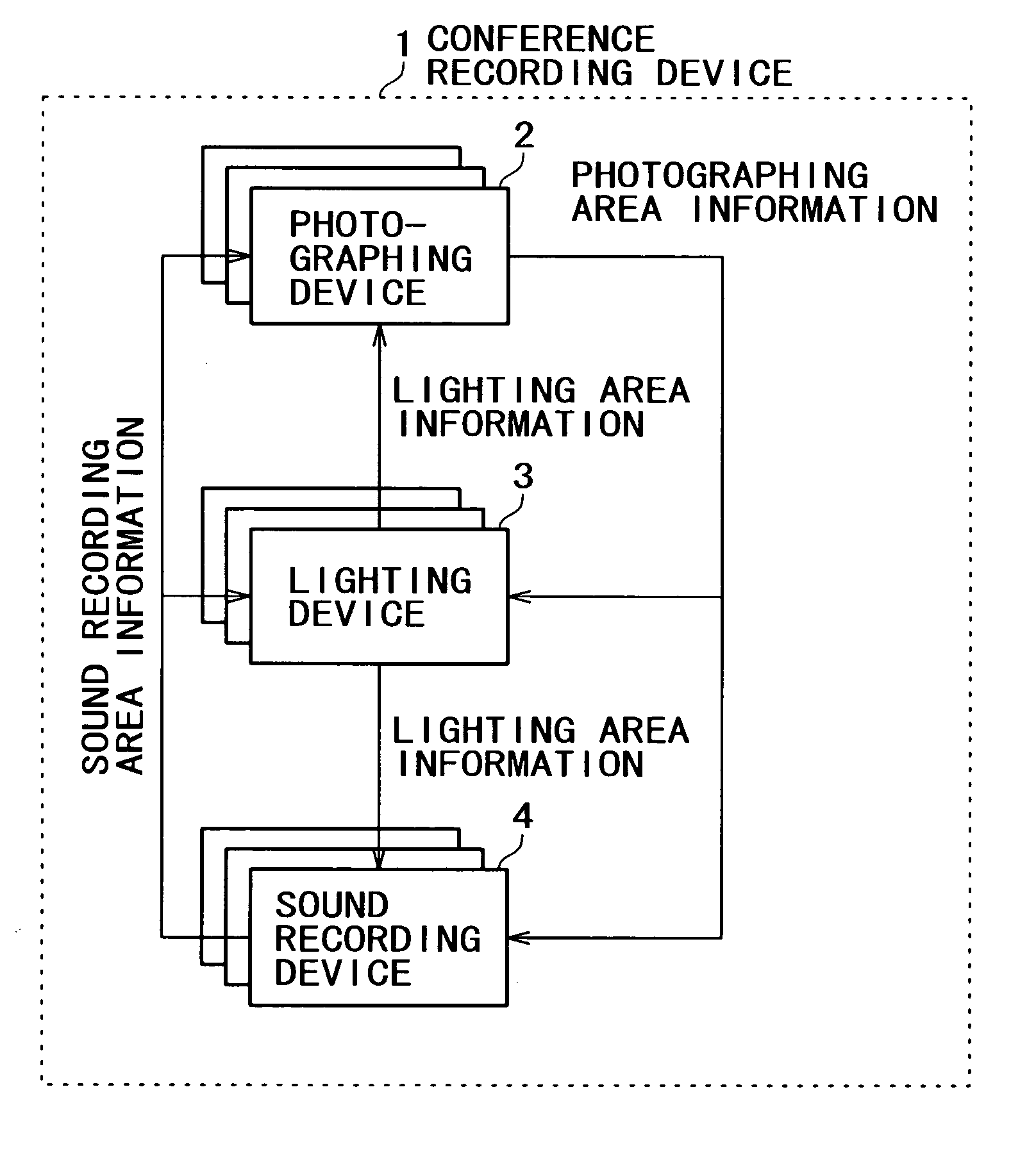
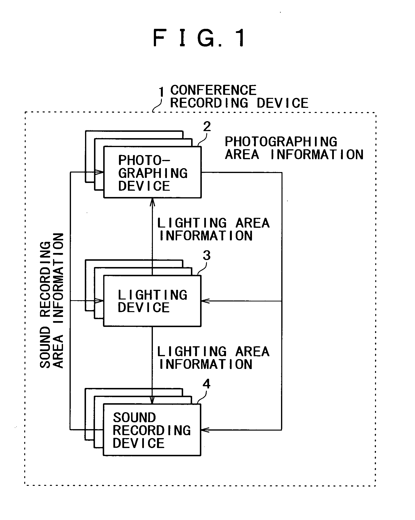
[0046]FIG. 1 is a block diagram showing an example of the construction of a conference recording device according to a first embodiment. As shown in FIG. 1, a conference recording device 1 includes photographing devices 2, lighting devices 3, and sound recording devices 4. The photographing devices 2, the lighting devices 3, and the sound recording devices 4 are provided in plural numbers.
[0047] The photographing devices 2 refer to photographing area information of each photographing device, lighting area information of each lighting device, and sound area information of each sound recording device, generates photographing area information representative of a photographing area of each photographing device so that each photographing device cooperatively photographs an photographing object, and controls the photographing area by use of the photographing area information. The lighting devices 3 refer to photographing area information of each photographing device, lighting area inform...
second embodiment
[0157] The following describes a second embodiment. A photographing area of the photographing device 2, a lighting area of the lighting device 3, and a sound recording area of the sound recording device 4 are modeled in cubes, and the photographing device 2, the lighting device 3, and the sound recording device 4 are controlled by use of the model of the cubes. A conference room, as shown in FIG. 15, is divided by cubes having a side of a prescribed unit length. For example, a conference room 50 is divided by 18 cubes as shown in FIG. 15. FIG. 15 is a drawing showing the conference room 50 divided by cubes. Next, an identifier is assigned to each of the divided cubes. For example, the individual cubes are defined by identifiers of BOX1 to BOX18, respectively. Then, the photographing device 2, the lighting device 3, and the sound recording device 4 are assigned as a photographing area, a lighting area, or a sound recording area that cover different cubes different from each other.
[0...
third embodiment
[0173] The following describes a third embodiment. The following describes a design device according to the third embodiment. FIG. 21 is a block diagram showing an example of the design device of the third embodiment. A design device 201 includes a control part 202, an operation part 203, a design data storage part 204, a display part 205, a photographing area information input part 206, a photographing area information storage part 207, a lighting area information input 208, a lighting area information storage part 209, a sound recording area information input part 210, a sound recording area information storage part 211, a participant information input part 212, a participant information storage part 213, a furniture information input part 214, a furniture information storage part 215, an environment information input part 216, and an environment information storage part 217.
[0174] The design device 201 designs design objects such as furniture including a conference room, a white...
PUM
 Abstract
Description
Claims
Application Information
 - R&D
- Intellectual Property
- Life Sciences
- Materials
- Tech Scout
- Unparalleled Data Quality
- Higher Quality Content
- 60% Fewer Hallucinations
Browse by: Latest US Patents, China's latest patents, Technical Efficacy Thesaurus, Application Domain, Technology Topic, Popular Technical Reports.
© 2025 PatSnap. All rights reserved.Legal|Privacy policy|Modern Slavery Act Transparency Statement|Sitemap|About US| Contact US: help@patsnap.com


