Crown molding with improved mounting surfaces

a technology of mounting surfaces and crown molding, which is applied in the direction of fixed installation, lighting and heating equipment, walls, etc., can solve the problems of failing to teach the lateral groove system used with the prior art longitudinal grooves

Inactive Publication Date: 2005-11-17
HAHN RICHARD
View PDF9 Cites 10 Cited by
  • Summary
  • Abstract
  • Description
  • Claims
  • Application Information

AI Technical Summary

Benefits of technology

[0017] Crown molding strips are manufactured in a wide range of sizes, decorative styles, and are made of various materials. Common materials are wood, plaster and plastics. However, the installation and durability of such crown moldings suffer from three deficiencies; first standard moldings, even those with longitudinal grooves do not have adequate groove structure for uniformly spreading bonding agents, as such agents need to be able to move lateral

Problems solved by technology

Our prior art search with abstracts described above teaches molding systems with longitudinal grooves, but fails to teach a lateral groove system used with the prior art longitudinal grooves.
However, the installation and durability of such crown moldings suffer from three deficiencies; first standard moldings, even those with longitudinal grooves do not have adequate groove structure for uniformly spreading bonding agents, as such agents need to be able to mov

Method used


Image

  • Crown molding with improved mounting surfaces
  • Crown molding with improved mounting surfaces
  • Crown molding with improved mounting surfaces

Examples


Embodiment Construction

[0029] The above described drawing figures illustrate the described apparatus and its method of use in at least one of its preferred, best mode embodiment, which is further defined in detail in the following description. Those having ordinary skill in the art may be able to make alterations and modifications what is described herein without departing from its spirit and scope. Therefore, it must be understood that what is illustrated is set forth only for the purposes of example and that it should not be taken as a limitation in the scope of the present apparatus and method of use.

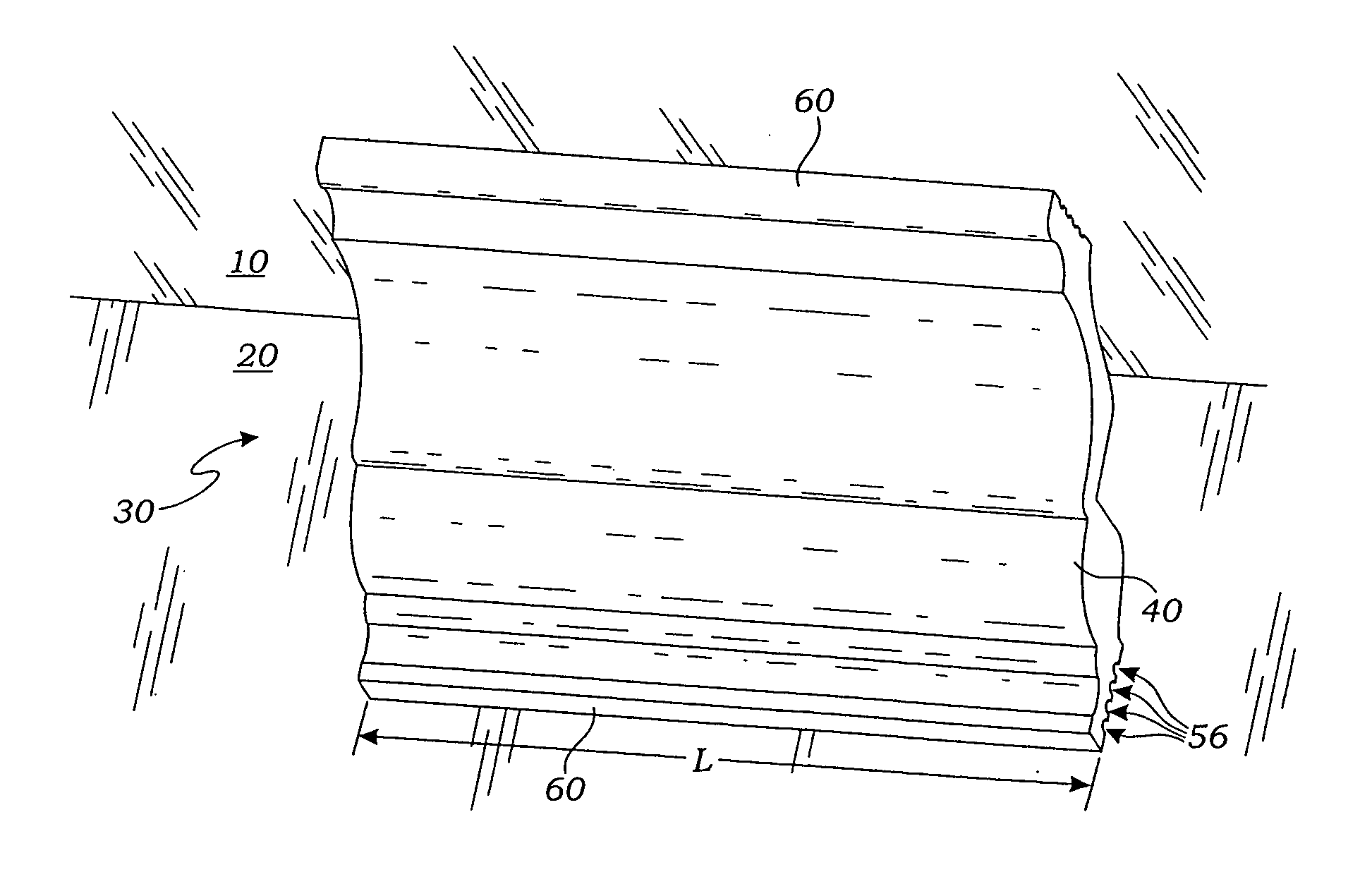
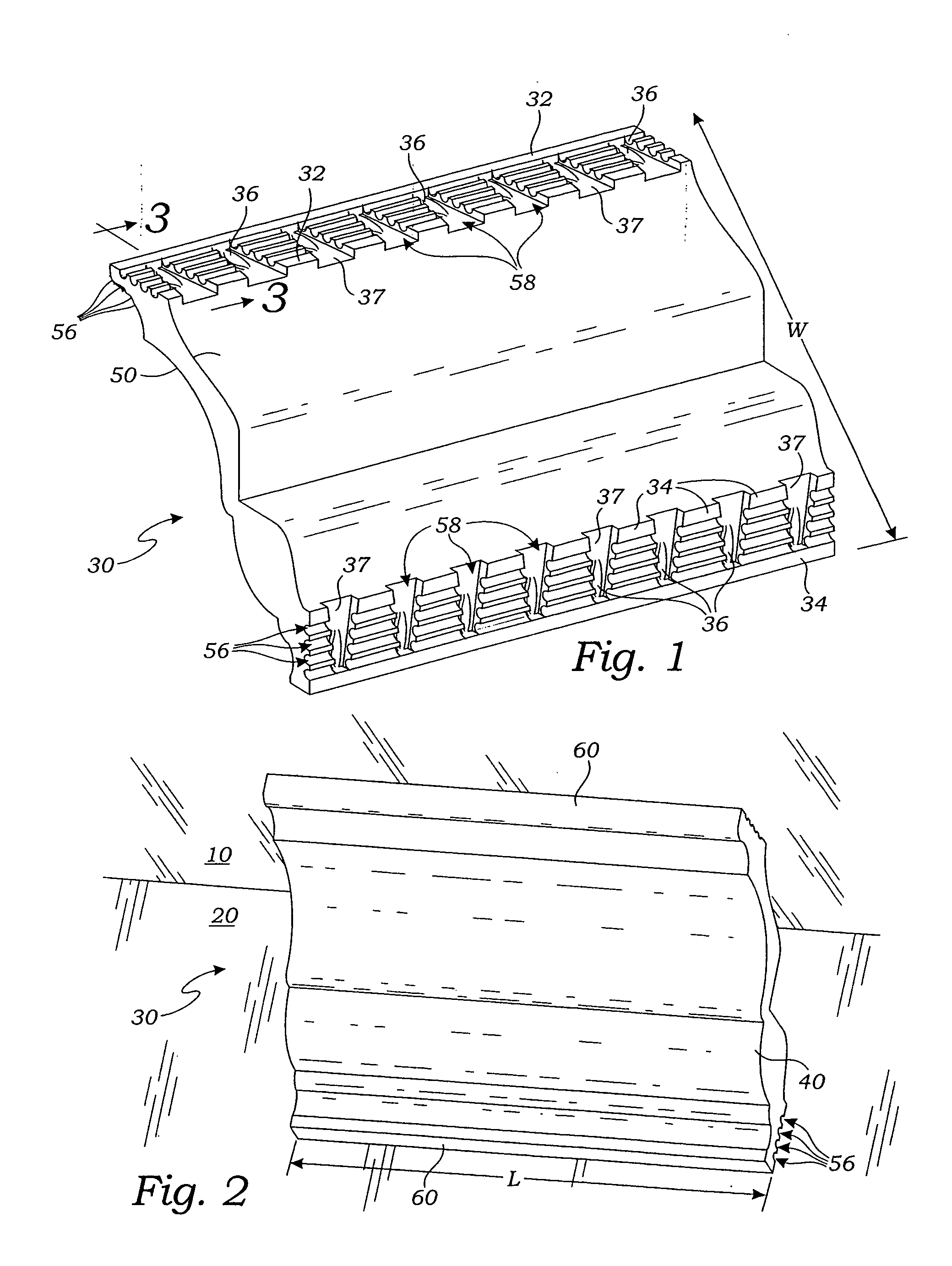
[0030] The apparatus described below and shown in the accompanying drawing figures is a crown molding which is mounted at the intersection of a ceiling surface 10 and an adjacent wall surface 20 of a room, as is well known in the art. The apparatus is preferably a molded unit 30 made of plaster or plastic materials and having a length “L”, shown in FIG. 2, establishing a longitudinal direction of the unit...


PUM


Abstract

A crown molding unit for engagement with a ceiling surface and an adjacent wall surface of a room has a first surface positioned for flush contact with a ceiling surface and simultaneously, a second surface positioned for flush contact with a wall surface. Each of the first and the second surfaces provide a plurality of side-by-side parallel longitudinal grooves and a plurality of side-by-side parallel lateral grooves, the lateral grooves lie orthogonal to the longitudinal grooves and converge to a depression in the apparatus.

Description

BACKGROUND [0001] 1. Related Applications [0002] This application is a Continuation In Part Application of a prior filed application having serial number 10359381 and filing date of Feb. 5, 2003 and entitled: Wall Molding Mounting Structure And Method; and is related to serial number 10810936 filed on Mar. 26, 2004. [0003] 2. Field of the Present Disclosure [0004] This disclosure relates generally to crown molding systems for the improvement of appearance and decoration of interior living spaces, and more particularly to a crown molding system having improved installation and durability features. [0005] 3. Description of Related Art [0006] The following art defines the present state of this field and each disclosure is hereby incorporated herein by reference: [0007] Reeves et al., U.S. 2002 / 0050104, discloses a eave closure for tile roofing has a nailing flange having a surface extending along a length of the closure, a planar riser potion contiguous with the nailing flange at an an...

Claims


Application Information

Patent Timeline
IPC IPC(8): E04B2/00F21S4/00F21S8/00F21V7/00F21V9/08F21V11/12F21V33/00
CPCE04F19/0436E04F19/0477E04F19/0495E04F2019/0418E04F2019/044F21V33/006F21S4/005F21V7/0008F21V7/0016F21V9/08F21V11/12E04F2019/0454F21S4/22
Inventor HAHN, RICHARD
Owner HAHN RICHARD
Why Eureka
Try Eureka