

End pumped slab laser cavity
- Summary
- Abstract
- Description
- Claims
- Application Information
AI Technical Summary
Benefits of technology
Problems solved by technology
Method used
Image

Examples
Embodiment Construction
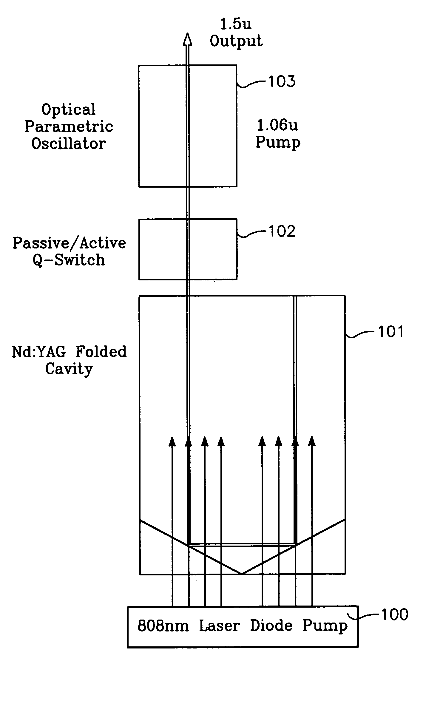
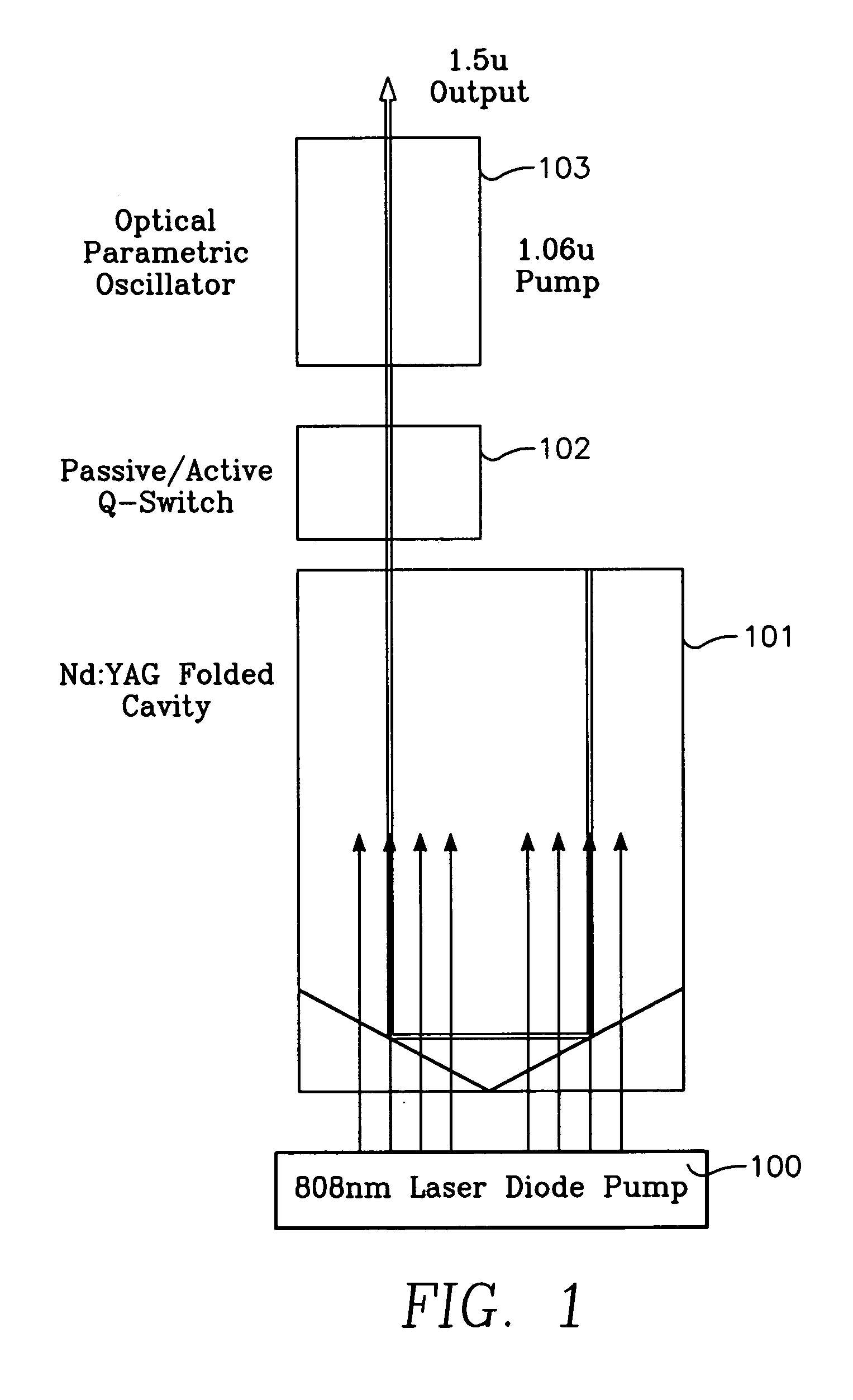
[0010] The present invention includes several optical components fused into one ‘block’ or pseudo-monolithic laser cavity. It is termed “pseudo-monolithic” since many components are incorporated into the structure. The proposed invention is named ‘End Pumped Slab’ because of its design is intended for laser diode pumping from the end, even though for higher energy diode pumping from the sides is possible. FIG. 1 depicts the components of the End Pumped Slab Laser Cavity. As shown in FIG. 1 a laser diode pump 100 produces laser outputs to an Nd:YAG folded cavity 101. The output from Nd:YAG folded cavity 101 passes through a passive / active Q-switch 102 and then, through an optical parametric oscillator 103. The end result is an eye safe 1.5 μoutput.
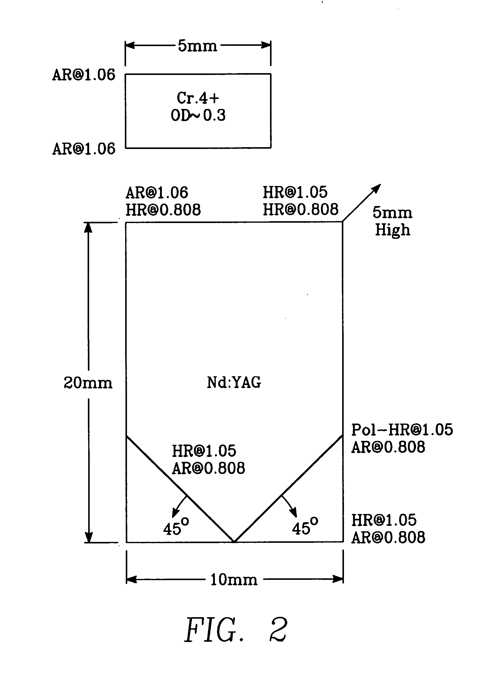
[0011] The optical components described above are bonded (diffusion or optical epoxy) to form one optical ‘block’. All components are pre-aligned during the crystal manufacturing process to form the optical laser cavity. The polarization c...
PUM
 Abstract
Description
Claims
Application Information