
Device for holding junction blocks in position

a technology of junction blocks and devices, applied in the direction of coupling device connections, electrical apparatus, coupling/disengagement of coupling parts, etc., can solve the problems of affecting the stability of the device, so as to reduce the clearance, reduce the effect of additional space occupation, and eliminate the effect of clearan

Inactive Publication Date: 2005-11-17
ENTRELEC
View PDF8 Cites 0 Cited by
  • Summary
  • Abstract
  • Description
  • Claims
  • Application Information

AI Technical Summary

Benefits of technology

"The present invention provides a device for holding in position junction blocks in a terminal strip on a support rail. The device includes a connecting part with immobilizing means at its ends that can accommodate a determined number of junction blocks pressed one against the other in a row. The connecting part consists of a plate more or less parallel to the support rail. The immobilizing means comprise at least one wedge that collaborates with a wall of a junction block situated at one end of the row. The device also includes catching means at each of its ends that can be fixed to the junction blocks situated at the two ends of the row. The catching means may include at least one moving hook or a fixed hook that can be compressed as the junction blocks are introduced between the immobilizing means. The parts of the device that are situated at the ends, outside of the part accommodating the junction blocks, are of dimensions, perpendicular to the support rail, that allow them to be housed under a separating end plate of the terminal strip formed by the junction blocks, and of dimensions, parallel to the support, smaller than those of this end plate. The technical effect of this invention is to ensure a constant separation between the junction blocks of a terminal strip while more or less eliminating the clearance between them and limited additional space occupation."

Problems solved by technology

However, junction blocks have some clearance between them particularly as a result of their being arranged on the rail by hand, as a result of defects of alignment, or as a result of molding residue on the faces of the blocks or on their studs that allow them to be kept aligned.
That makes the use of the plugs, shunts or other devices intended to interact with several junction blocks simultaneously difficult, the blocks having to be held in place by hand at least during the fitting phase, and then subjecting the device to stresses after assembly.

Method used


Image

  • Device for holding junction blocks in position
  • Device for holding junction blocks in position
  • Device for holding junction blocks in position

Examples


first embodiment

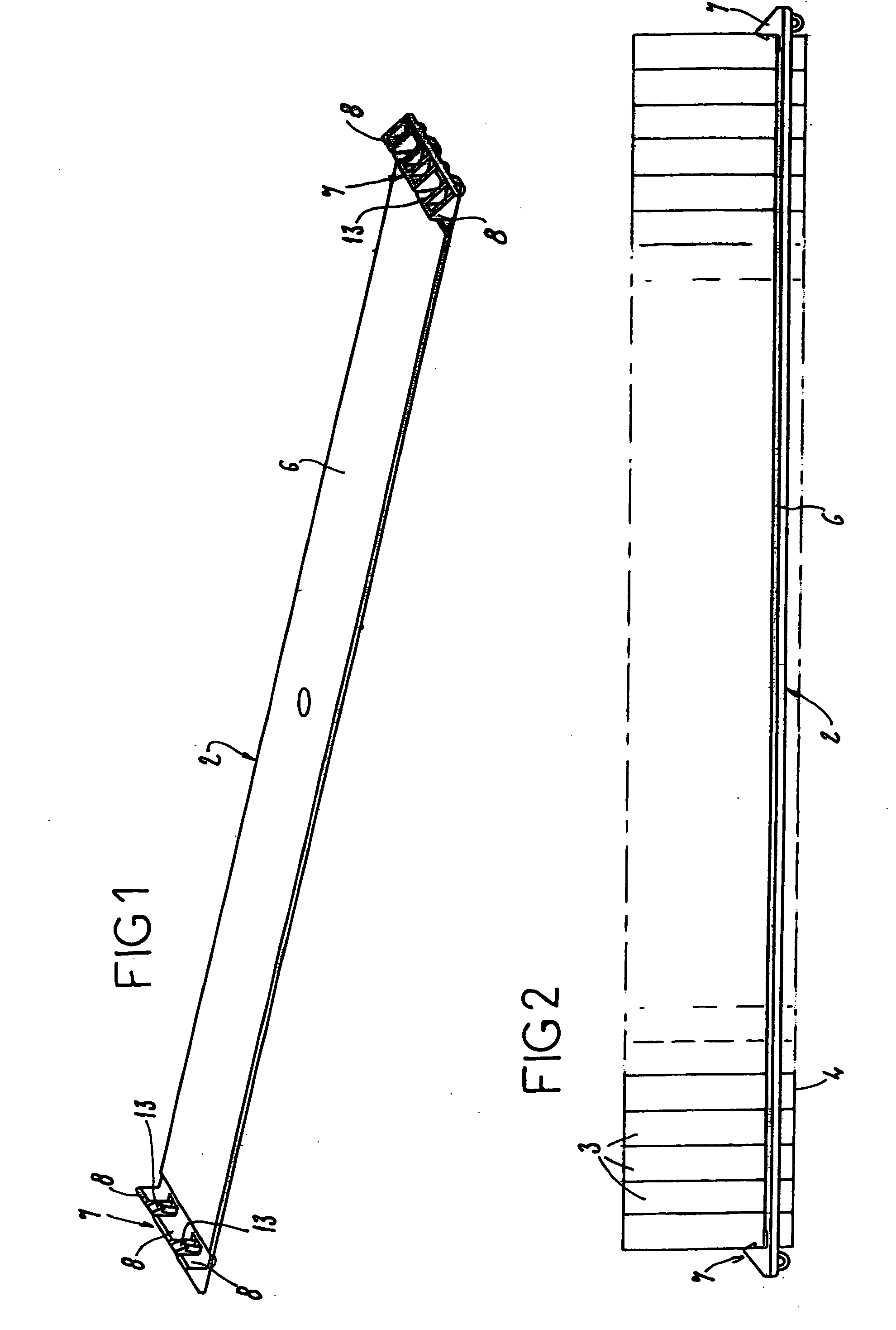
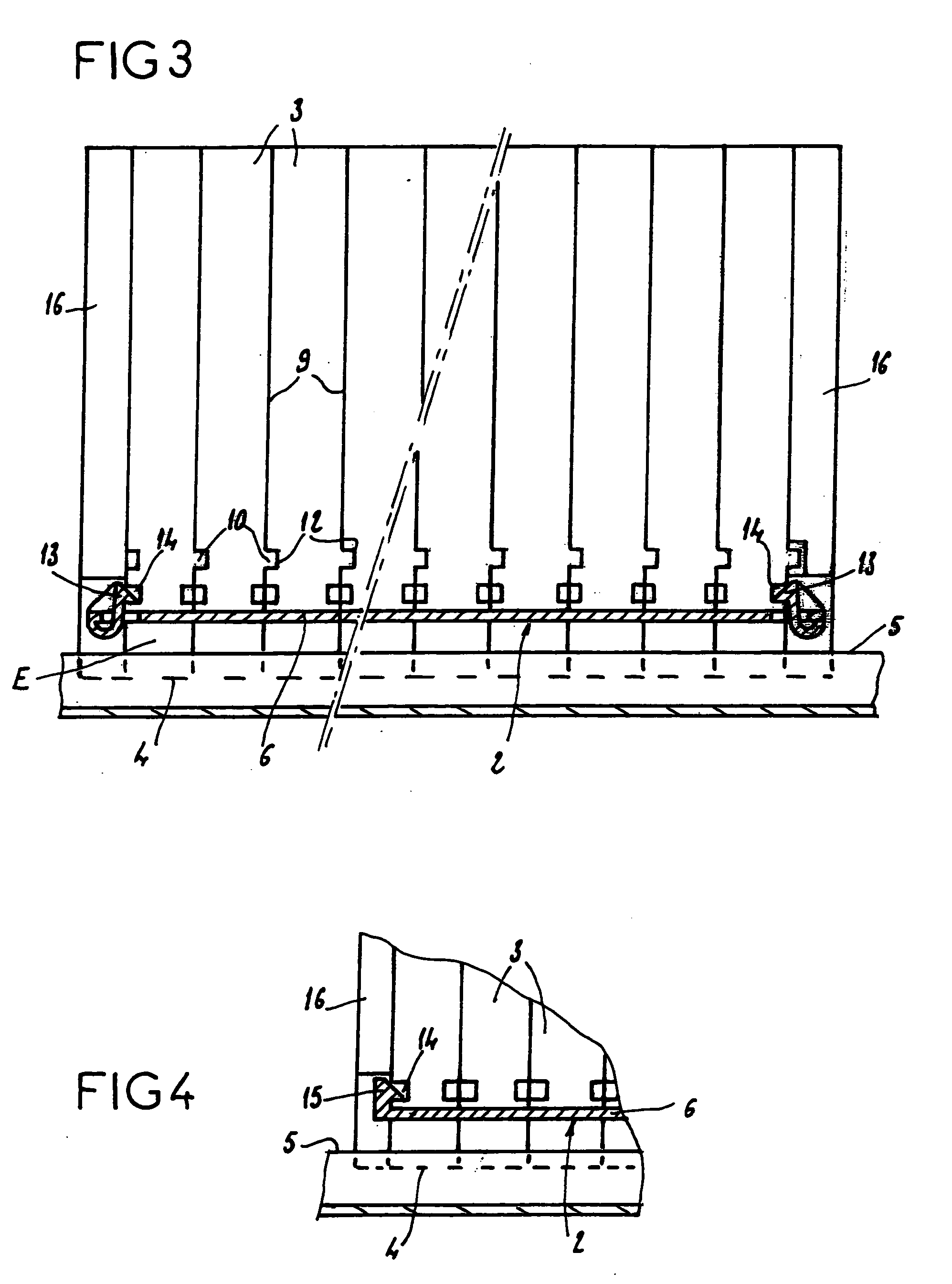
[0023] As depicted in FIGS. 1 to 3, a device 2 for holding in position junction blocks 3 intended to be fixed by a foot 4 onto a support of the rail type 5 comprises a connecting part consisting of a plate 6 more or less parallel to the support rail 5, equipped with immobilizing means 7 at its two ends, these consisting of wedges 8 intended to collaborate with a wall of a junction block 3 situated at one end of the row.

[0024] The immobilizing means 7 situated at the two ends allow a determined number of junction blocks 3 pressed one against another in a row to be housed between these two ends.

[0025] The junction blocks 3 are, in particular, joined together in an alignment in order to form a terminal strip allowing a collection of poles performing determined functions to be held together.

[0026] Each junction block 3 comprises, on one of its face 9 perpendicular to the support rail 5, a stud 10 intended to be housed in a cavity 12 of corresponding shape formed in the face opposite ...

second embodiment

[0030] depicted in FIG. 4, the device comprises the same elements except that the catching means consist of fixed hooks 15, secured to the immobilizing means, the row of junction blocks being compressed as the junction blocks are inserted between the immobilizing means, the hook becoming housed in a cavity in the end junction block 3 after insertion.

[0031] According to the two embodiments depicted in the figures, the wedges 8 and the hooks 13 or 15 situated at the ends of the plate have dimensions perpendicular to the rail that allow them to be housed under end plates 16 bounding at each end the terminal strip formed by the alignment of the junction blocks contained on the plate.

[0032] Furthermore, the wedges 8 and the hooks 13 or 15 have a dimension in the direction of the rail more or less equal to that of an end plate, allowing them thus not to protrude from the end plate 16 when the latter is in position. In this way, it is possible for other junction blocks 3 or other element...


PUM


Abstract

Device for holding in position junction blocks which are fixed by a foot onto a support of the rail type, particularly to form a terminal strip, and which comprises a connecting part equipped with immobilizing means at its two ends able to accommodate, between these two ends, a determined number of junction blocks pressed one against the other in a row.

Description

BACKGROUND OF THE INVENTION AND DESCRIPTION OF THE PRIOR ART [0001] The present invention relates to a device for holding electrical junction blocks in position. [0002] A terminal strip for connecting electrical conductors is commonly made up of a collection of junction blocks arranged side by side in a row, the junction blocks being fixed to a support rail that allows the alignment to be maintained. [0003] Alignment may also be facilitated by the presence of studs on the junction blocks which can be housed in cavities of corresponding shape on the adjacent junction block in the row. [0004] Conducting elements such as shunts which allow several poles of the terminal strip to be maintained at the same potential, or plugs allowing a pole to be connected to a given electrical circuit may be connected to the terminal strips thus formed. A shunt or a plug comprising several pins must be used in the face of several terminals spaced apart by a determined spacing. [0005] Furthermore, comple...

Claims


Application Information

Patent Timeline
Patent Type & Authority Applications(United States)
IPC IPC(8): H01R9/26
CPCH01R9/2616H01R9/2608
Inventor DA SILVA, FRANCKJOURDAN, BENOIT
Owner ENTRELEC
Learn More