
Rotating display device and electrical apparatus employing the same

a display device and display device technology, applied in the field of electric devices, can solve the problems of difficult to accurately read or interpret by users, and difficulty in reading the value displayed on the display

Inactive Publication Date: 2005-11-24
EATON CORP
View PDF6 Cites 24 Cited by
  • Summary
  • Abstract
  • Description
  • Claims
  • Application Information

AI Technical Summary

Benefits of technology

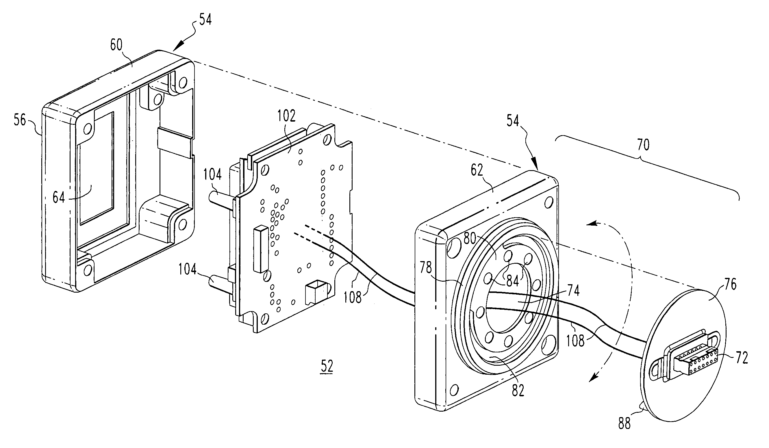
The present invention provides a rotating display device that can be rotated to display a value from an electrical apparatus in a proper viewing orientation regardless of the position of the electrical apparatus. This allows for easy viewing of the display regardless of the position of the electrical apparatus. The rotating display device includes a housing, a display, and a rotating assembly, which allows for the display to rotate. The electrical apparatus includes an enclosure and a connector for outputting a value, which can be received by the rotating display device and displayed in a variable viewing orientation. The rotating display device can be mounted to the exposed surface of the electrical apparatus. The technical effects of the invention include improved viewing of the display and ease of use with various electrical apparatus.

Problems solved by technology

This has made it difficult to read the value displayed on the display when the electrical apparatus is disposed in any orientation other than a vertical one.
This would result in the electrical current value being displayed in an improper orientation making it difficult to be accurately read or interpreted by a user.

Method used


Image

  • Rotating display device and electrical apparatus employing the same
  • Rotating display device and electrical apparatus employing the same
  • Rotating display device and electrical apparatus employing the same

Examples


Embodiment Construction

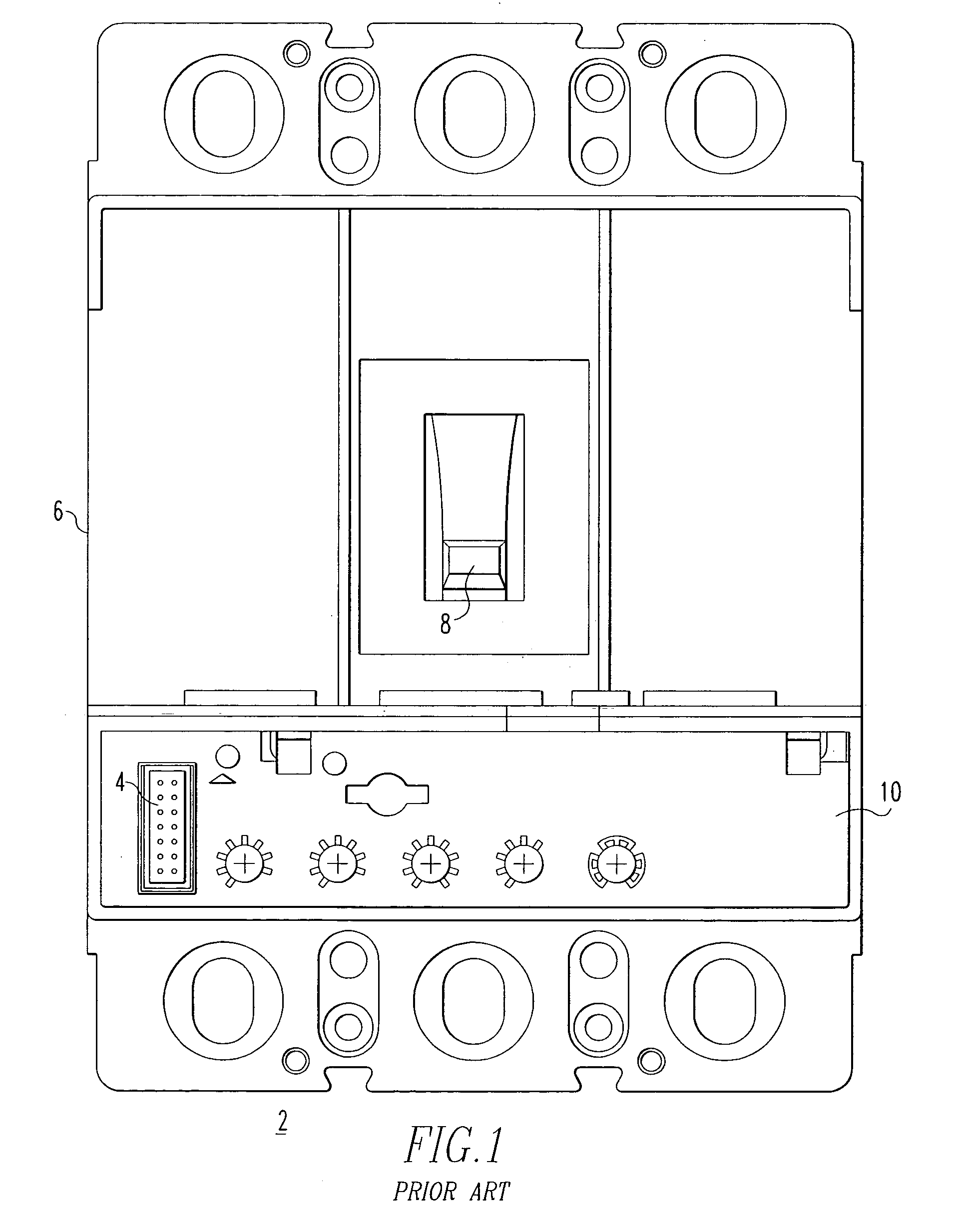
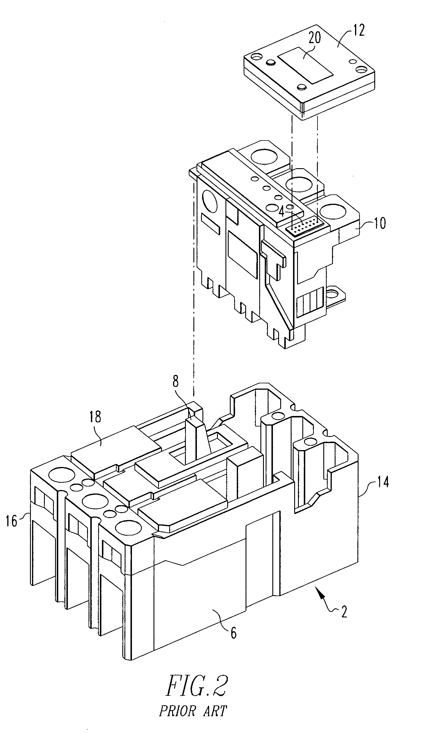
[0021] For purposes of illustration, the invention will be described as applied to rotating display devices for displaying a value received from the test port of a low voltage circuit breaker trip unit, although it will become apparent that it could also be applied to other types of circuit breakers (e.g., without limitation, residential circuit breakers; power circuit breakers; molded case circuit breakers), which output a value on a port (e.g., a connector), as well as to other electrical apparatus such as, for example, circuit switching devices and other circuit interrupters such as contactors, motor starters, motor controllers and other load controllers, which output a value on a port (e.g., a connector).

[0022] As employed herein, the statement that two or more parts are “coupled” together shall mean that the parts are joined together either directly or joined through one or more intermediate parts.

[0023] As employed herein, the term “fastener” refers to any suitable fastening...


PUM


Abstract

A rotating display device displays a value in a variable viewing orientation. The value is received from an electrical apparatus, such as a circuit breaker, having a first port. The rotating display device includes a housing having a first side and a second side, a display disposed on the first side of the housing, a rotating assembly disposed on the second side, and a second port for receiving the value from the first port of the electrical apparatus. The second port communicates with the display and is coupled to the rotating assembly in order to permit the display to rotate. The rotating assembly permits the rotating display device to rotate in the plane of the surface of the circuit breaker on which it is mounted, thereby permitting the display to be quickly and accurately viewed and interpreted regardless of the orientation of the surface to which it is coupled.

Description

BACKGROUND OF THE INVENTION [0001] 1. Field of the Invention [0002] The present invention relates generally to electrical apparatus and, more particularly, to a display device for receiving and displaying a value from an electrical apparatus. The invention also relates to an electrical apparatus including a display device. [0003] 2. Background Information [0004] Displaying operating parameters (e.g., without limitation, voltage; electrical current; frequency) provides one way for a user to ensure that an electrical apparatus is operating properly. Accordingly, electrical apparatus including electrical switching apparatus, such as circuit switching devices and circuit interrupters (e.g., without limitation, circuit breakers, contactors, motor starters, motor controllers and other load controllers), often include a connector for outputting a value. The value outputted on the connector is typically indicative of one or more operating parameters. Circuit breakers, such as the low voltag...

Claims


Application Information

Patent Timeline
Patent Type & Authority Applications(United States)
IPC IPC(8): H01H71/02H01H71/12H02B1/32H05K5/00
CPCH01H71/0228H01H2071/006H01H71/123
Inventor PUSKAR, MICHAEL P.WHITAKER, THOMAS A.CARLINO, HARRY J.SHAAK, TODD M.
Owner EATON CORP
Learn More