Modular surface mount manifold

a module and manifold technology, applied in the direction of bends, valve housings, servomotors, etc., can solve the problems of reducing the efficiency of welding operations, and reducing the amount of expensive materials used. , the effect of reducing the amount of expensive materials used

Inactive Publication Date: 2005-12-01
SWAGELOK CO
View PDF61 Cites 19 Cited by
  • Summary
  • Abstract
  • Description
  • Claims
  • Application Information

AI Technical Summary

Benefits of technology

[0006] Thus it is desired that a modular manifold design be provided which eliminates the seals between modular mating blocks, dramatically reduces the amount of expensive material utilized, and results in a simpler and cheaper system to manufacture while providing a reduced system footprint or envelope which meets or surpasses the performance, integrity and reliability of existing systems.

Problems solved by technology

These connections are undesirable in many applications because they add additional time and cost for welding operations, unnecessary space between components and make it difficult to replace a component located between other components.
Further, these systems are typically custom designed and manufactured which make the manufacturing costs and procurement of replacement parts quite expensive.
One disadvantage to these type of prior art modular systems is that the entire modular block is made of high purity metal.
Thus money and natural resources are inefficiently utilized Further, these block components also have higher manufacturing costs due to the complexity of machining multiple passageways of a single block as well as a higher risk of expensive scrap being formed due to the manufacturing complexity.
Further, the mating blocks require the use of mating seals therebetween, which require additional manufacturing time, and further require proper installation and makeup torque of the fastener members in order to ensure a leak-tight seal.

Method used


Image

  • Modular surface mount manifold
  • Modular surface mount manifold
  • Modular surface mount manifold

Examples


Embodiment Construction

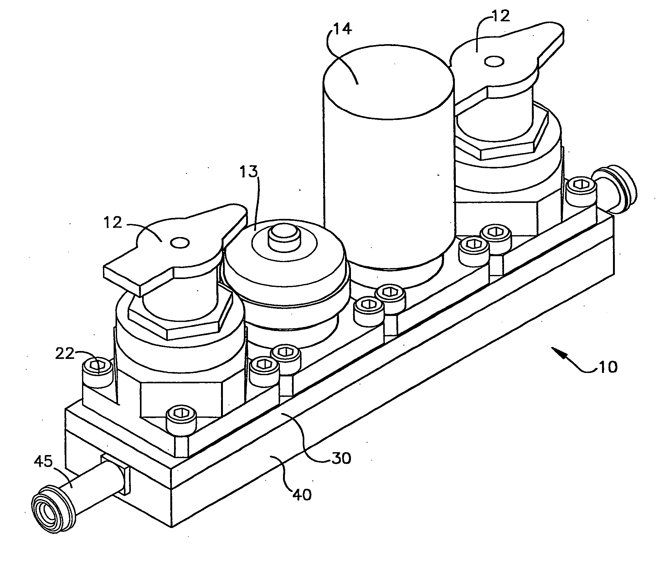
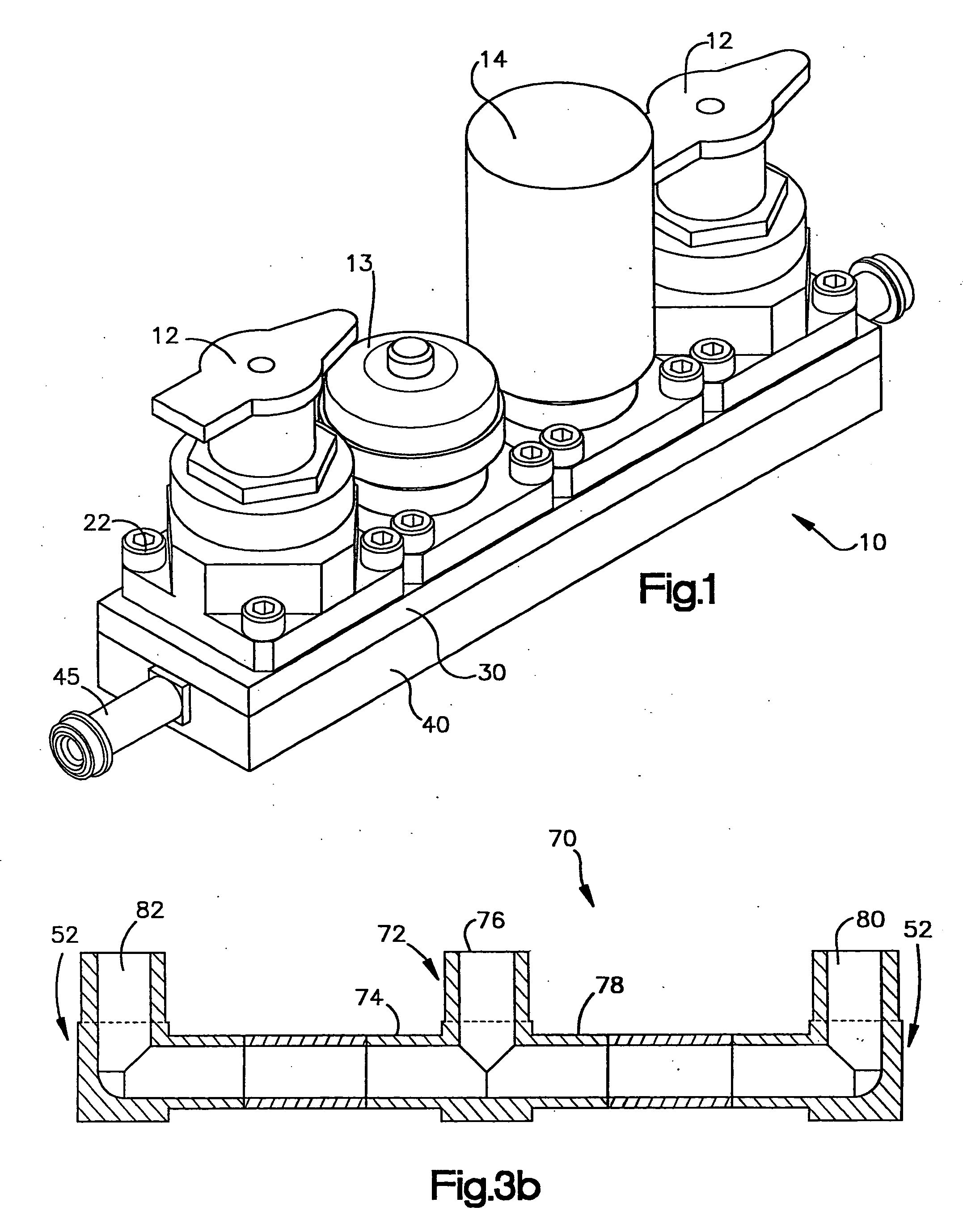
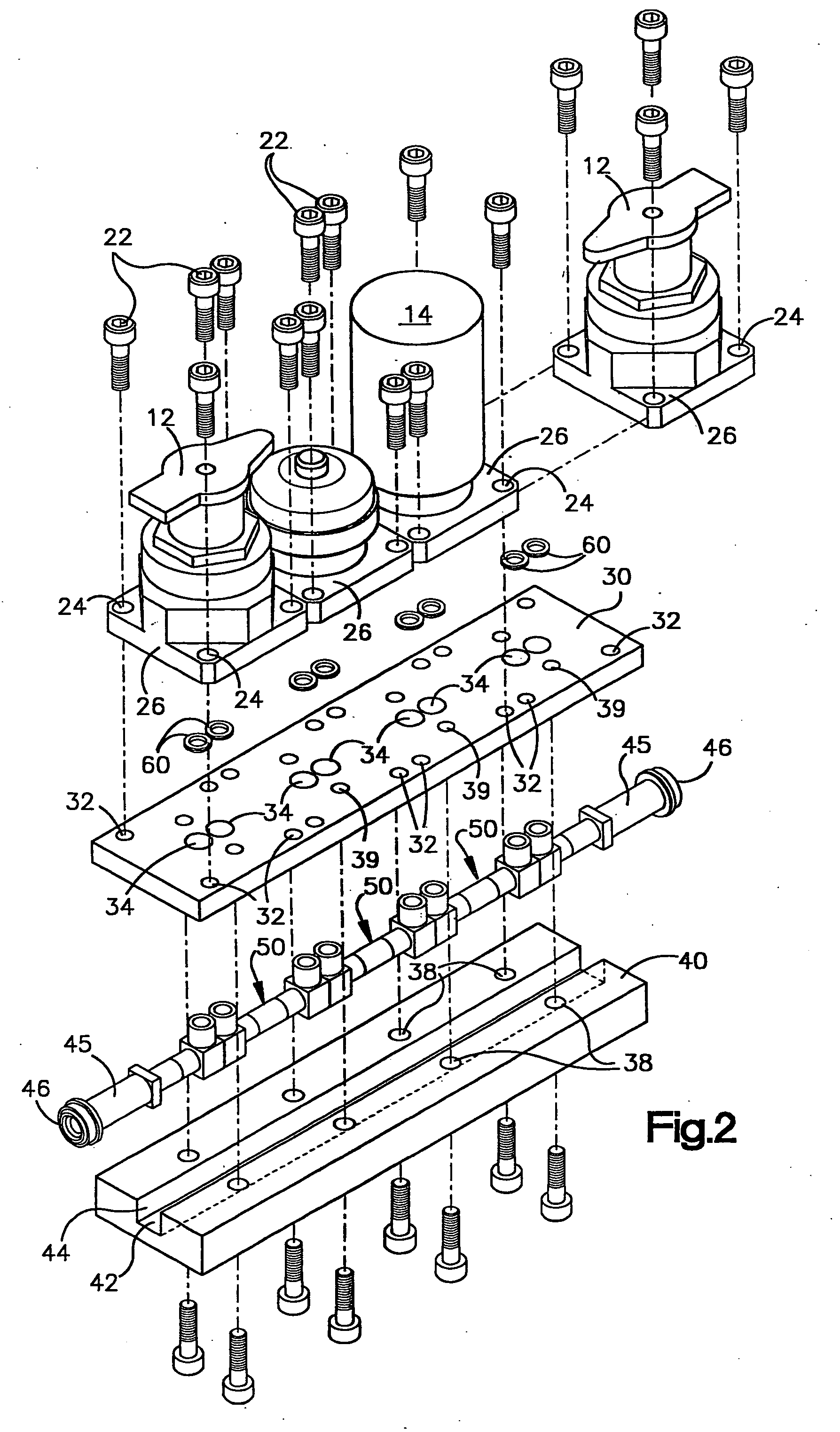
[0019] Referring now to the drawings wherein the drawings are for the purposes of illustrating the preferred embodiments of the invention only and not for purposes of limiting same, a unique manifold system is shown in the FIGS. 1-4. The inventions as shown and described in the Figures are useful, for example, as part of a high purity modular gas distribution system used in the manufacture of semiconductor devices or other fluid systems which must withstand corrosive fluids. The present invention is not limited to the use in high purity fluid systems, and may be useful in any application relating to fluid flow control.

[0020] Now referring to the drawings and more particularly FIG. 1, a modular fluid manifold system 10 is shown assembled together with fluid flow control components such as valves 12, flow regulators 13, filters 14 and the like. The fluid components may be utilized in conjunction with the invention, but are not part of the invention. The fluid components 12-14 are pre...


PUM


Abstract

A modular manifold system is provided for interconnecting fluid components of a fluid system in a reduced area The system is comprised of a one or more bridge fittings having an internal fluid passageway which has an inlet end in fluid communication with an outlet port of a first fluid component, and an outlet end in fluid communication with an inlet port of a second fluid component. The bridge fittings may be mounted within a channel of a backing plate for structural support. An optional locator plate may be utilized which is mounted over the ends of the bridge fittings in order to align the inlet and outlet ports of the fluid components with the inlet and outlet ends of the bridge fittings. The bridge fittings may also be mounted to the locator plate in multiple directions forming multiple flow paths. Additionally, the bridge fittings may be stacked to form multiple layers where bridge fittings of one layer may be in fluid communication with bridge fittings of another layer. The invention may further comprise seals provided in a recess between the fluid ports and the mating bridge fittings ends.

Description

FIELD OF THE INVENTION [0001] The invention relates in general to manifolds for fluid systems, and more particularly, the invention relates to a modular gas distribution system for use in high purity fluid systems and corrosive fluid systems such as the clean room environment used to manufacture semiconductor wafers. BACKGROUND OF THE INVENTION [0002] This application claims the benefit of U.S. provisional application No. 60 / 076,871 filed on Mar. 5, 1998. [0003] To manufacture semiconductors, the industry uses various high purity gases. These gases are controlled by systems made up of high purity valves, regulators, pressure transducers, mass flow controllers and other components connected together by welding and high purity metal seal fittings. These connections are undesirable in many applications because they add additional time and cost for welding operations, unnecessary space between components and make it difficult to replace a component located between other components. Furt...

Claims


Application Information

Patent Timeline
Patent Type & Authority Applications(United States)
IPC IPC(8): F15B11/00F15B13/00F15B13/08F16K11/10F16K27/00F16L39/00
CPCF15B13/0807F15B13/0814F16K27/003F15B13/086F15B13/0892F15B13/0825Y10T137/87885Y10T137/5109F16K27/00
Inventor EIDSMORE, PAUL E.
Owner SWAGELOK CO
Why Eureka
Try Eureka