Modular surface mount manifold assemblies

a module and manifold technology, applied in valve housings, mechanical equipment, transportation and packaging, etc., can solve the problems of reducing the efficiency of manifold assembly, reducing the amount of expensive materials used, and adding additional time and cost for welding operations, so as to achieve a simple and less expensive system manufacturing, the effect of eliminating the seal

Inactive Publication Date: 2006-05-02
SWAGELOK CO
View PDF66 Cites 11 Cited by
  • Summary
  • Abstract
  • Description
  • Claims
  • Application Information

AI Technical Summary

Benefits of technology

[0007]Thus it is desired that a modular manifold design be provided which eliminates the seals between modular mating blocks, dramatically reduces the amount of expensive material utilized, and results in a simpler and less expensive system to manufacture while providing a reduced system footprint or envelope which meets or surpasses the performance, integrity and reliability of existing systems.

Problems solved by technology

These connections may be undesirable in some applications because they add additional time and cost for welding operations, unnecessary space between components and make it difficult to replace a component located between other components.
Further, these systems are typically custom designed and manufactured which make the manufacturing costs and procurement of replacement parts quite expensive.
One disadvantage to these type of prior art modular systems is that the entire modular block is made of high purity metal.
Further, these block components also have higher manufacturing costs due to the complexity of machining multiple passageways of a single block as well as a higher risk of expensive scrap being formed due to the manufacturing complexity.
In addition, the mating blocks require the use of mating seals therebetween, which require additional manufacturing time, and further require proper installation and makeup torque of the fastener members in order to ensure a leak-tight seal.

Method used


Image

  • Modular surface mount manifold assemblies
  • Modular surface mount manifold assemblies
  • Modular surface mount manifold assemblies

Examples


Embodiment Construction

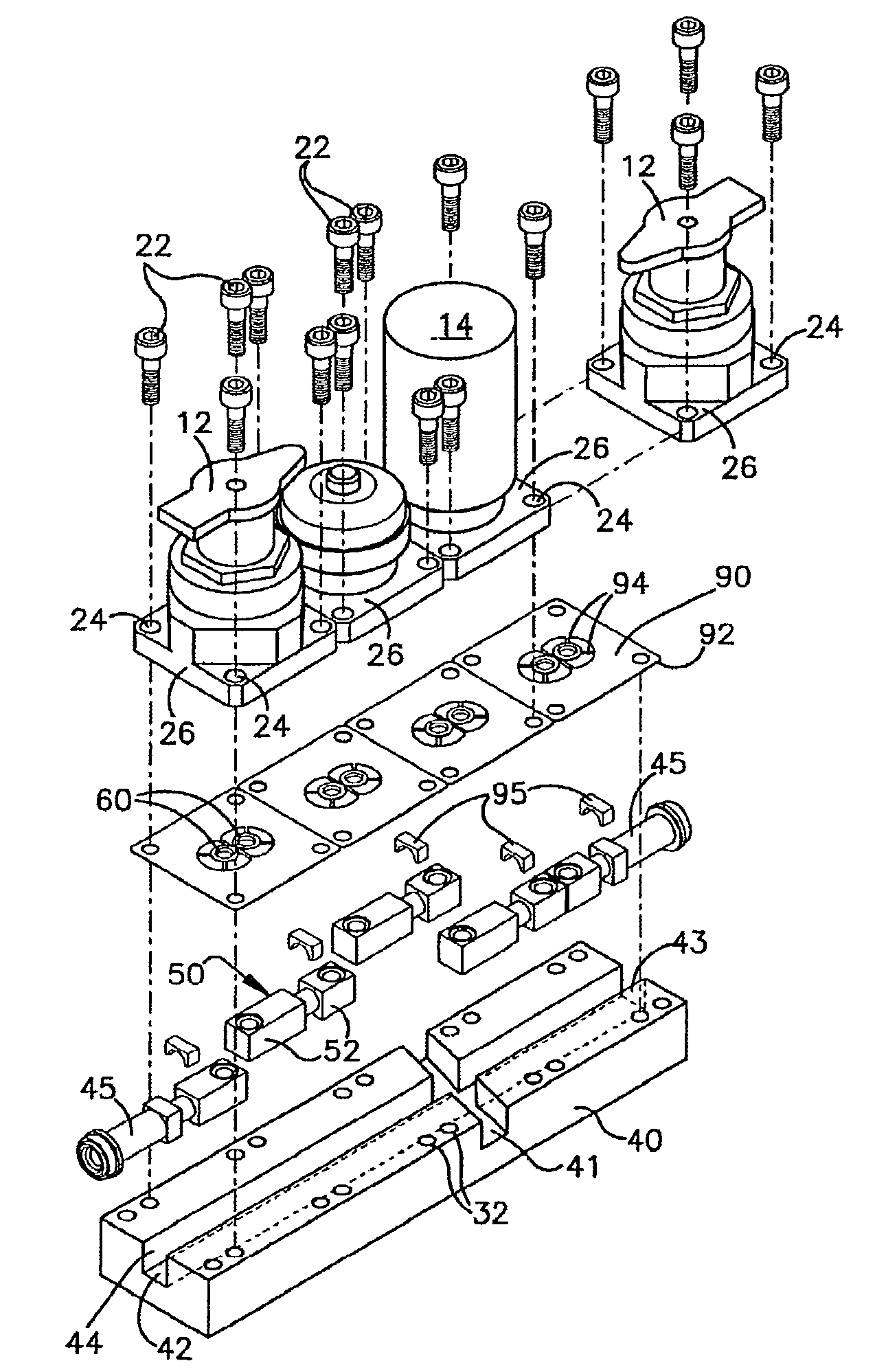
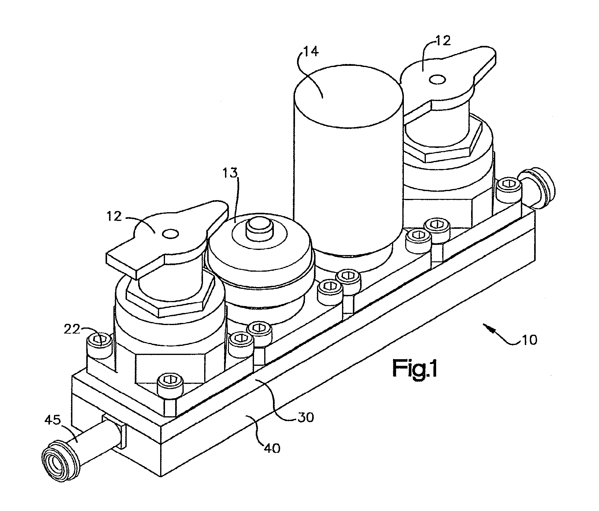
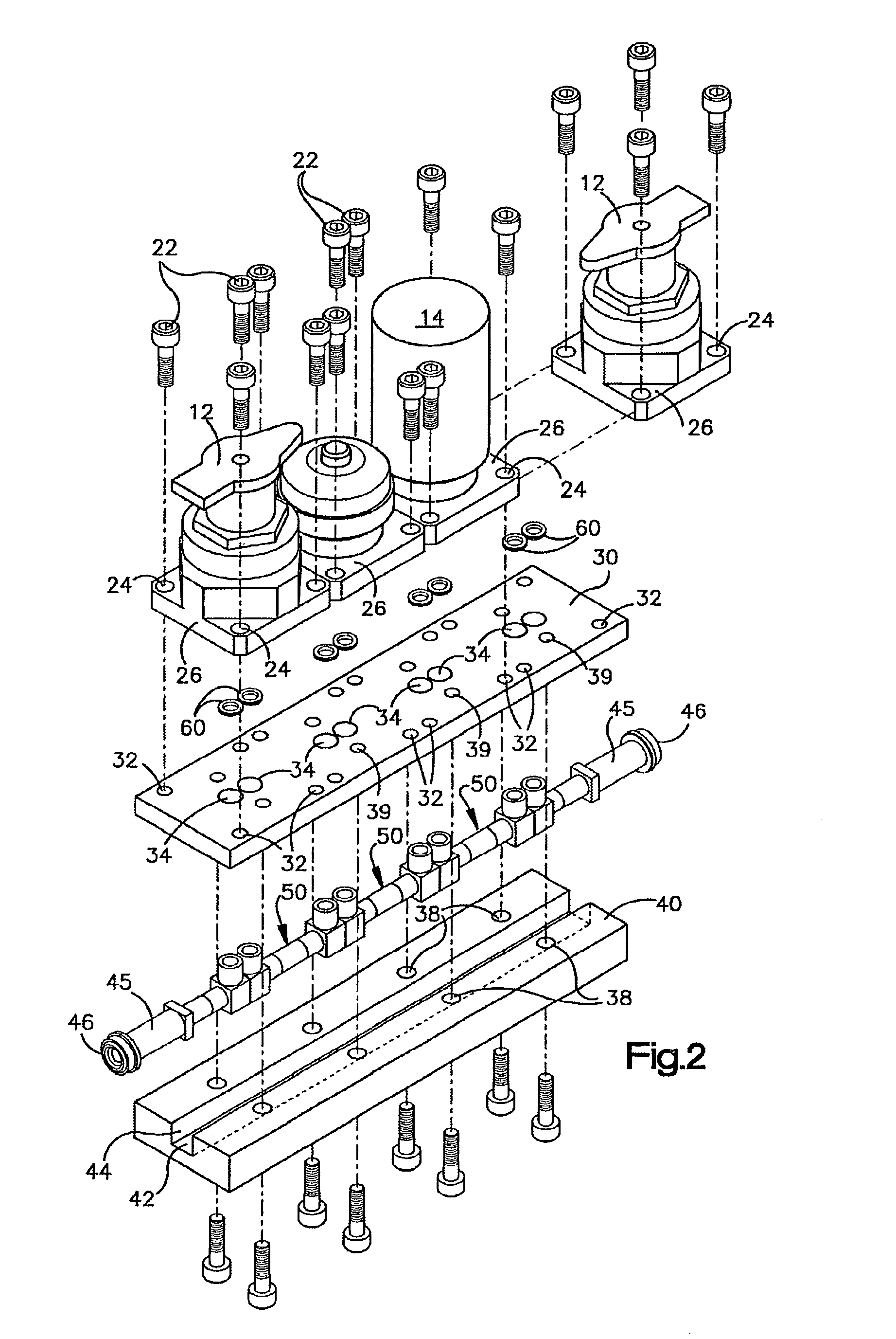
[0048]Referring now to the drawings wherein the drawings are for the purposes of illustrating the preferred embodiments of the invention only and not for purposes of limiting same, a unique manifold system is shown in the FIGS. 1–30. The inventions as shown and described in the Figures are useful, for example, as part of a high purity modular gas distribution system used in the manufacture of semiconductor devices or other fluid systems which must withstand corrosive fluids. The present invention is not limited to the use in high purity fluid systems, and may be useful in any application relating to fluid flow control. Additionally, the various aspects of the present invention shown and described herein may be used separately or in various combinations as required for a particular application. Furthermore, although the preferred embodiments are described herein with reference to an exemplary modular manifold design, those skilled in the art will readily understand the invention can ...


PUM


Abstract

A modular manifold system is provided for interconnecting fluid components of a fluid system in a reduced area. The system is comprised of a one or more bridge fittings having an internal fluid passageway which has an inlet end in fluid communication with an outlet port of a first fluid component, and an outlet end in fluid communication with an inlet port of a second fluid component. The bridge fittings may additionally comprise two or more ports, which one of said ports may be in fluid communication with a manifold on another substrate level. The bridge fittings may be mounted within a channel of a backing plate for structural support or in channel blocks of varying sizes. The bridge fittings may also be mounted to the locator plate in multiple directions forming multiple flow paths. The bridge fittings may be stacked to form multiple layers.

Description

[0001]CROSS REFERENCE TO RELATED APPLICATIONS[0002]This application is a continuation of U.S. patent application Ser. No. 09 / 544,020 for MODULAR SURFACE MOUNT MANIFOLD ASSEMBLIES filed on Apr. 6, 2000, now U.S. Pat. No. 6,629,546, which is a continuation of International patent application No. PCT / US99 / 10980 filed on May 18, 1999 which designated the U.S., and which was a continuation in part of International patent application No. PCT / US99 / 04972 filed on Mar. 5, 1999. This application further claims the benefit of U.S. provisional application No. 60 / 085,817 filed on May 18, 1998 and U.S. provisional application No. 60 / 102,277 filed on Sep. 29, 1998.BACKGROUND OF INVENTION[0003]The invention relates in general to manifolds for fluid systems, and more particularly, the invention relates to a modular gas distribution system for use in high purity fluid systems and corrosive fluid systems such as gas systems used, for example, to manufacture semiconductor wafers.[0004]To manufacture se...

Claims


Application Information

Patent Timeline
Patent Type & Authority Patents(United States)
IPC IPC(8): F16K11/10F16K27/00
CPCF16K27/003Y10T137/87885
Inventor EIDSMORE, PAUL G.MOHLENKAMP, MICHAEL J.OLECHNOWICZ, BENJAMIN J.SCHILT DEINES, CHRISTINE M.NORDSTROM, DOUGLASMCCOY, JAMES
Owner SWAGELOK CO
Why Eureka
Try Eureka