Improved Toilet Flushing System

a technology for toilets and flushing systems, applied in flushing devices, water installations, constructions, etc., can solve problems such as leakage of water fill valves, water wastage, and flapper valve leakag

Pending Publication Date: 2022-09-22
PRASAD HARI
View PDF6 Cites 0 Cited by
  • Summary
  • Abstract
  • Description
  • Claims
  • Application Information

AI Technical Summary

Benefits of technology

[0020]eliminates the flapper seal between the tank and the bowl that are prone to leak;
[0023]allows the user to reset the system to fill the reservoir for every flush after the system's water flow is shut off;
[0026]eliminates condensation on the water tank surface occurring in existing systems;
[0027]can be mounted at a higher elevation than that of a ceramic tank that is mounted right on top of the bowl. Water from higher elevation increases the velocity in which water enters the bowl resulting in better flushing of bowl surface. This is especially true when the quantity of the flushing water is restricted;
[0028]allows the use of more than one reservoir to eliminate wait time between flushes or if additional water is required for a flush;
[0033]No toilet flushing system that eliminates all failure modes in a simplistic arrangement of systems that is cost effective is available today.

Problems solved by technology

Failure mode and effects analysis is performed on the components the failure of which result in water wastage.
Due to deterioration of materials or physical deformation or entrapment of foreign object between the sealing surface, flapper valves leak.
Water fill valve: leak due to deterioration of seal or engagement.

Method used


Image

  • Improved Toilet Flushing System
  • Improved Toilet Flushing System
  • Improved Toilet Flushing System

Examples


Embodiment Construction

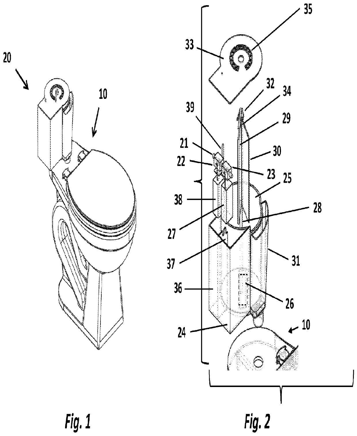
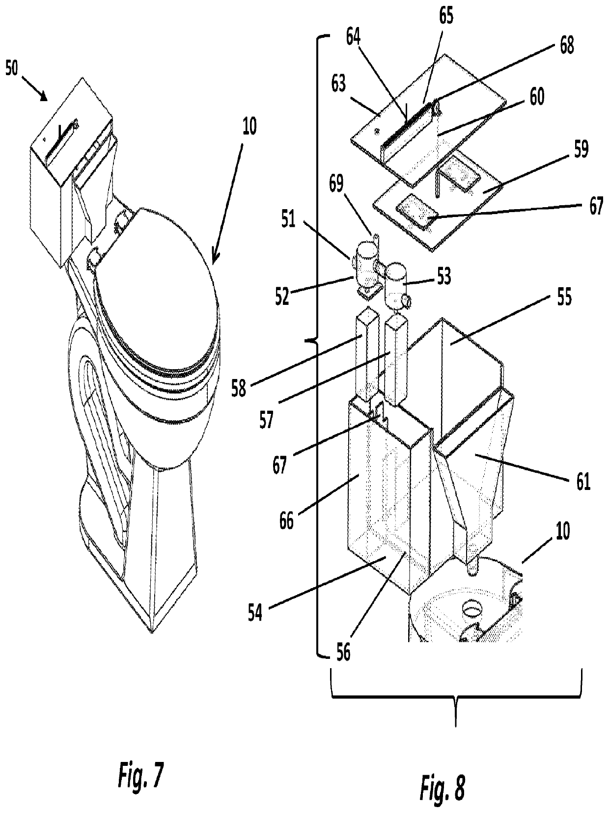
[0080]The components used in this invention include a receiver, displacer, master valve, fill valve, leak arrest system and alert-reset. These components can be assembled in numerous combinations. The difference the types of each component and the method in which they are linked contribute to the variations in the multitude of embodiments.

[0081]The following are the variations in the components in the system.

[0082]The receivers and displacers can be of different shapes and sizes.

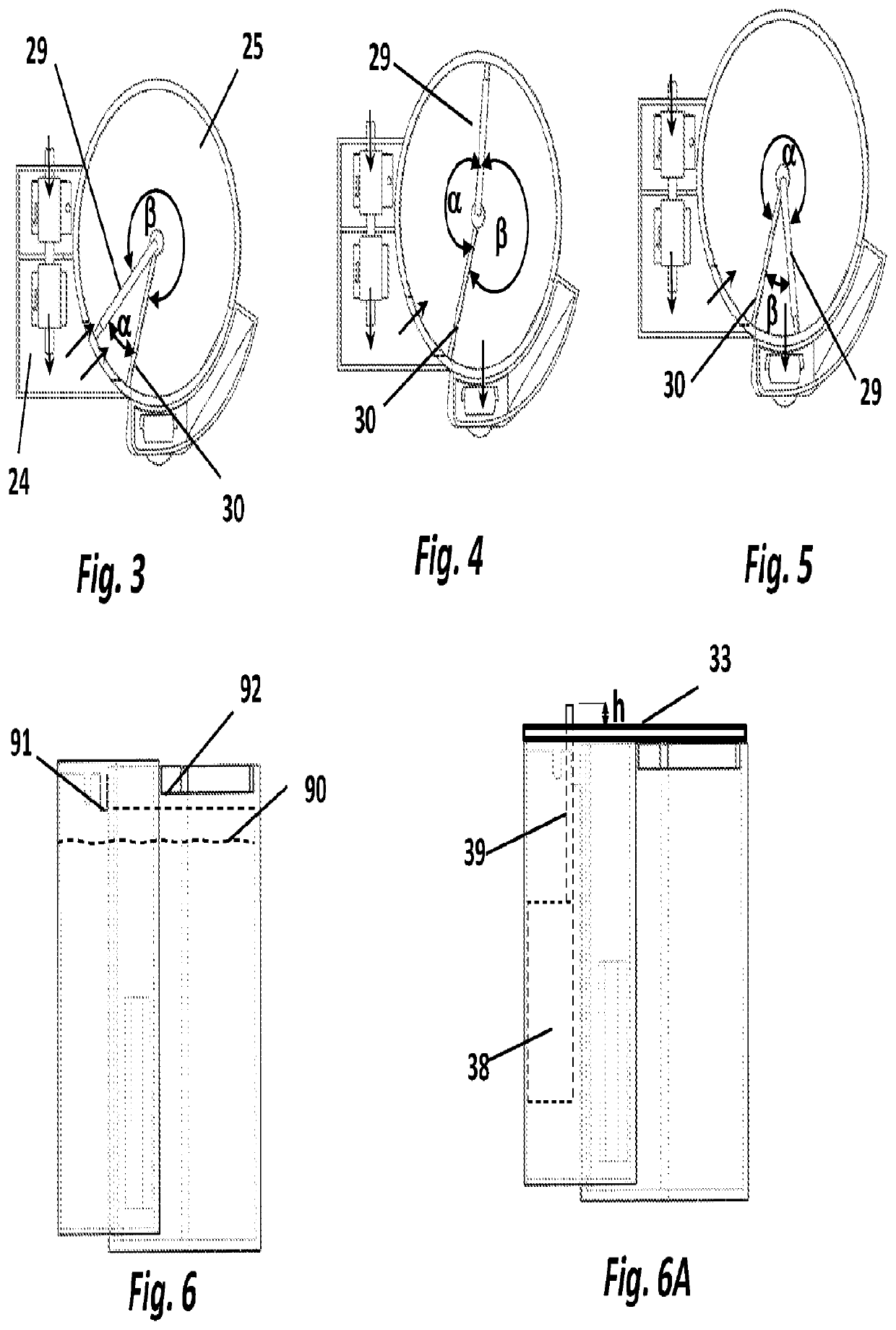
[0083]The methods of displacing water from the receiver for flushing such as tilting the receiver or using a displacer. The actuation mechanisms of flushing using a handle, or a motor operated by a switch or an electronic control system. The electronic control system with inputs including push buttons, touch screen, voice, light, radio signals, blue tooth, etc.

[0084]Valve types include plug valve, diaphragm valve, globe valve, gate valve that are operated mechanically or electromechanically.

[0085]The means o...


PUM


Abstract

A toilet flushing system comprising a cylindrical receiver into which flush water is received through a fill valve; a float operating within a float chamber that is fluidly connected to said cylindrical receiver to open and close said fill valve according to the water level in said cylindrical receiver; and a displacer rotatably attached to an axis inside said cylindrical receiver to displace any required fraction of water from said cylindrical receiver into a bowl relative to the angle of rotation.

Description

TECHNICAL FIELD[0001]The present invention relates to toilet or urinal flushing systems.BACKGROUND OF THE INVENTION[0002]Today's most commonly used toilet flushing systems have the following short comings that need to be solved:[0003]Toilets are prone to leak.[0004]Small water leaks from the tank into the bowl or urinal goes unidentified unless close attention is paid.[0005]No visible or audible alerts when water from the flush tank leaks into the bowl;[0006]Identified water leaks often get ignored due to apathy or financial restraints of the user resulting in water wastage;[0007]Only two choices exist regarding the quantity of flush water dispensed into the bowl, half or full;[0008]Due to government mandated water restrictions reduced water usage per flush the efficiency of flushing is diminished;[0009]Condensation (sweating) occurs on the toilet tank due to the temperature difference between the tank and the surrounding whereby the condensate drains onto the floor resulting in wat...

Claims


Application Information

Patent Timeline
Patent Type & Authority Applications(United States)
IPC IPC(8): E03D5/02E03D1/33
CPCE03D5/026E03D1/33E03D1/20E03D1/14E03D1/26E03D1/00E03D1/32E03D5/09E03D1/30E03D11/11
Inventor PRASAD, HARI
Owner PRASAD HARI
Why Eureka
Try Eureka