Valve and spring for fluid filter

a fluid filter and valve spring technology, applied in the field of valve springs and valve springs for fluid filters, can solve the problems of costly and unusable assembly components of typical fluid filters, undesired valve operation, etc., and achieve the effect of reducing the overall size of the valve assembly, eliminating the seal, and reducing the number of valve assembly components

Inactive Publication Date: 2005-04-14
PUROLATOR ADVANCED FILTRATION
View PDF12 Cites 12 Cited by
  • Summary
  • Abstract
  • Description
  • Claims
  • Application Information

AI Technical Summary

Benefits of technology

[0007] The inventive arrangement significantly reduces the number of valve assembly components and eliminates the seal typically used between the center port

Problems solved by technology

As a result, a typical fluid filter uses numerous assembled components that are costly.
Furthermore, since so m

Method used


Image

  • Valve and spring for fluid filter
  • Valve and spring for fluid filter
  • Valve and spring for fluid filter

Examples


Embodiment Construction

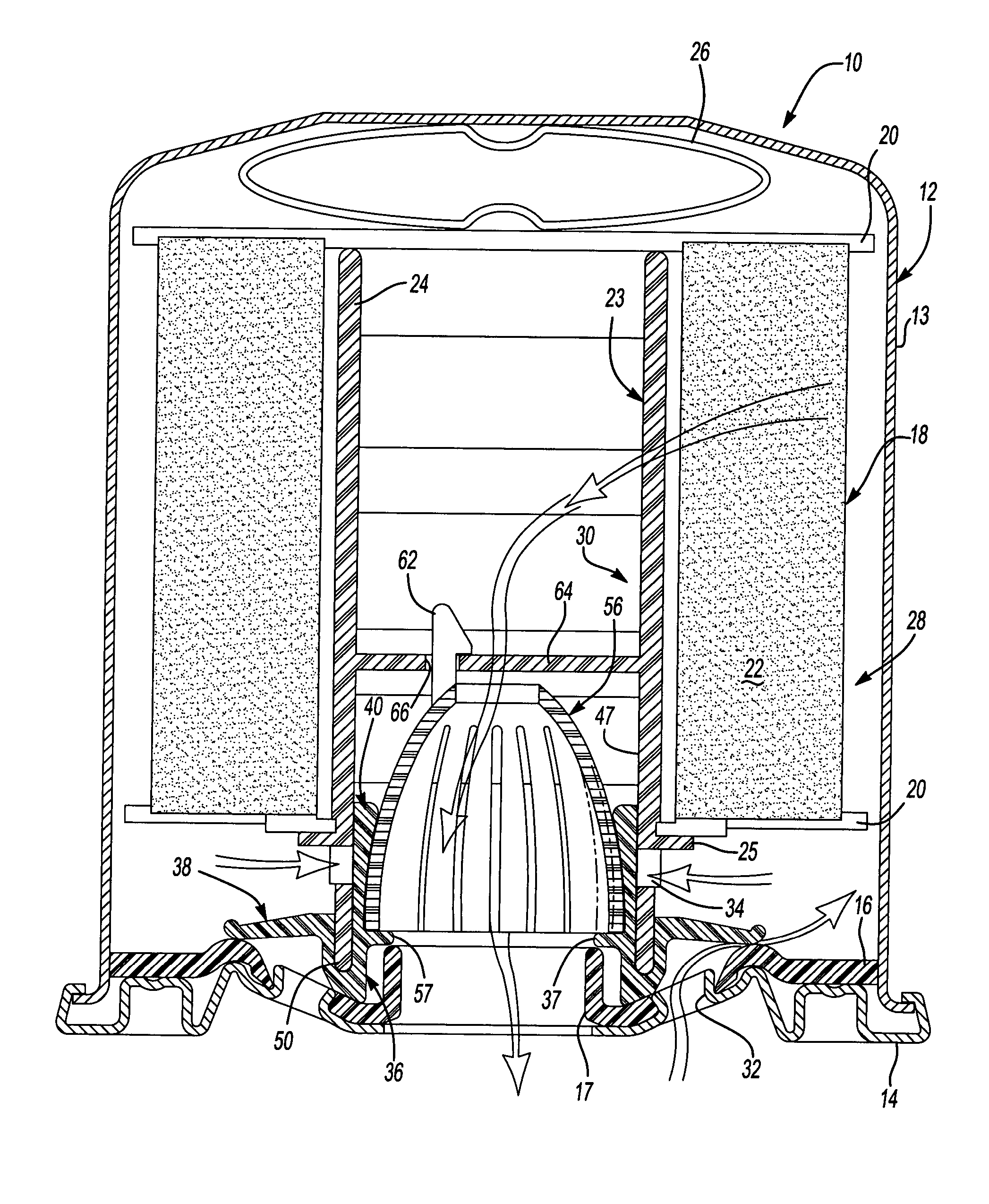
[0013] A fluid filter 10 is shown in FIG. 1. The filter 10 shown is suitable for use as a vehicle oil filter, however, this invention may be used in any fluid filter application. The filter 10 comprises a housing 12 including a can 13 with a retainer 14 secured to the open end of the can. The housing 12 also includes a tapping plate 16 typically arranged interiorly and adjacent to the retainer 14. The tapping plate 16 includes a central threaded hole 17 for securing the filter 10 to a structure having fluid passages that carry the fluid to and from a desired location such as a vehicle engine.

[0014] A filter assembly 18 is arranged within the housing 12. The filter assembly 18 includes end discs 20 having a filter media 22, such as a paper filter element, arranged between the end disc 20 in any suitable manner, which is well known in the art. The filter media 22 may define a central opening 23. Typically, the filter media 22 is a pleated paper element and may have a center tube 24 i...


PUM

PropertyMeasurementUnit
Forceaaaaaaaaaa
Pressureaaaaaaaaaa
Flow rateaaaaaaaaaa

Abstract

A fluid filter includes a housing having a tapping plate with a first aperture. A center tube is arranged in the housing proximate to the tapping plate. The center tube includes a second aperture. An elastomeric valve assembly is arranged between the center tube and the tapping plate. The valve assembly comprises an integrated, one-piece relief valve and anti-drain back valve. The anti-drain back valve is arranged adjacent to the first aperture for selectively blocking the first aperture to prevent fluid from exiting the inlet side of the filter during pressure drops. The relief valve is arranged adjacent to the second aperture for selectively blocking the second aperture to permit fluid to flow past the relief valve during high pressure conditions such as cold starts. A generally concave conical spring radially biases the relief valve closed.

Description

BACKGROUND OF THE INVENTION [0001] This invention relates to a fluid filter such as an oil filter, and more particularly, the invention relates to a valve and spring for fluid filters. [0002] Fluid filters such as oil filters typically include one or more valves to regulate the flow of fluid through the filter during various operating conditions. For example, the filter may incorporate an anti-drain back valve to prevent fluid from exiting the inlet side of the filter during a pressure drop thereby carrying debris from the filter element. A filter also may use a relief valve for permitting the fluid to bypass the filter element under high pressures, such as when the oil is very viscous during engine cold starts in oil filter applications. [0003] Many fluid filter valve configurations have been used. One common valve configuration uses a valve arranged near the tapping plate of the filter housing. A moveable piston is arranged adjacent to a fluid aperture. A coil spring biases the fl...

Claims


Application Information

Patent Timeline
IPC IPC(8): F02M37/22B01D27/10B01D35/02
CPCB01D27/103B01D2201/0415B01D27/106
Inventor CLINE, L. STEVEN
Owner PUROLATOR ADVANCED FILTRATION
Why Eureka
Try Eureka