Vehicle step tube

a technology for step tubes and vehicles, applied in vehicle components, deflectors, tobacco, etc., can solve the problems of significant labor and therefore expense, and the manufacture of coomber step tubes requires significant labor

Active Publication Date: 2005-12-01
STEFFENS ENTERPRISES
View PDF5 Cites 29 Cited by
  • Summary
  • Abstract
  • Description
  • Claims
  • Application Information

AI Technical Summary

Benefits of technology

[0005] The aforementioned problems are overcome by the present invention, wherein a step tube comprises a one-piece extrusion that includes a plurality of generally vertical ribs on its upper portion. The ribs vary in ...

Problems solved by technology

The Coomber step tube requires a considerable fabrication and assembly of multiple extruded compon...

Method used


Image

  • Vehicle step tube
  • Vehicle step tube
  • Vehicle step tube

Examples


Embodiment Construction

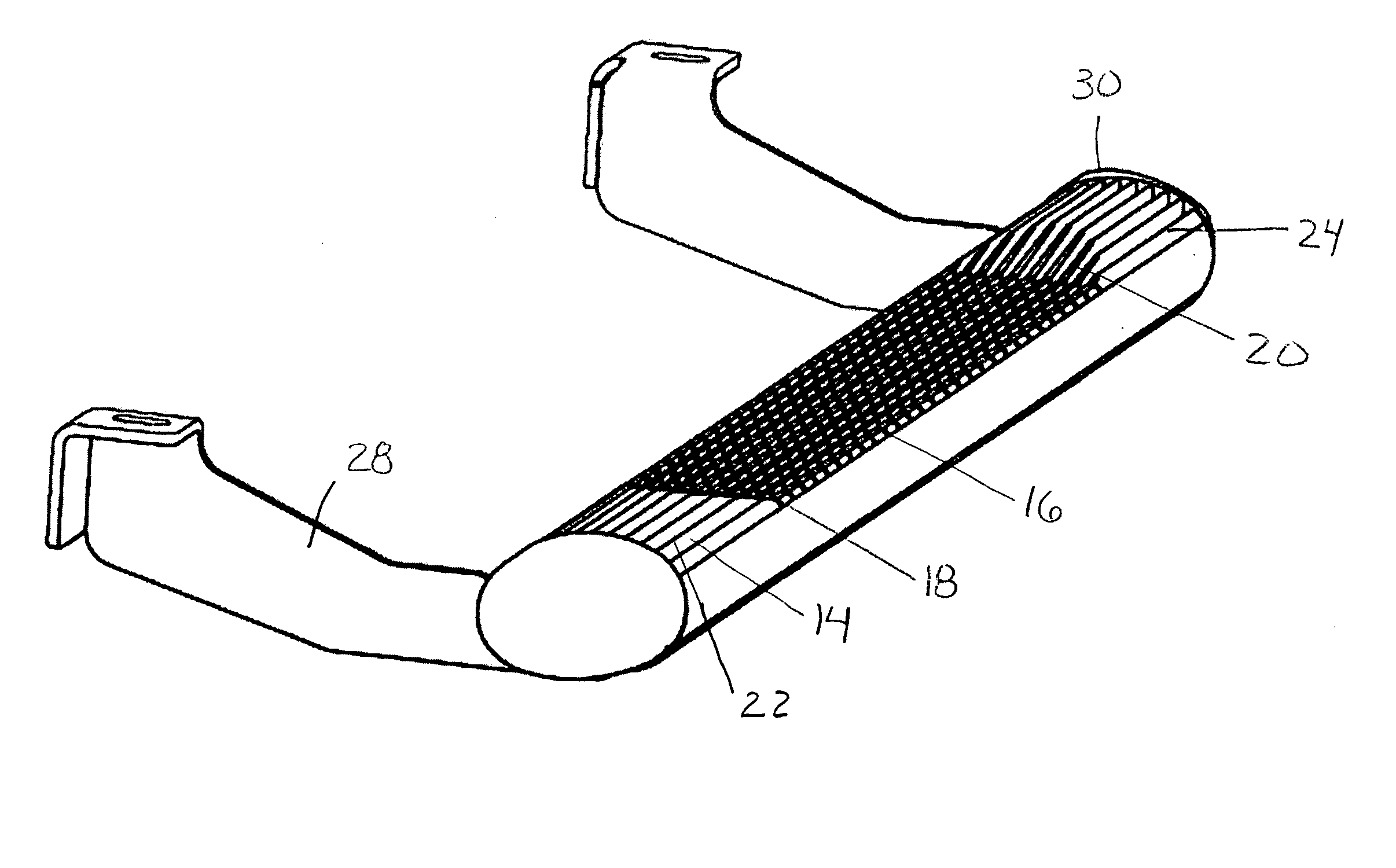
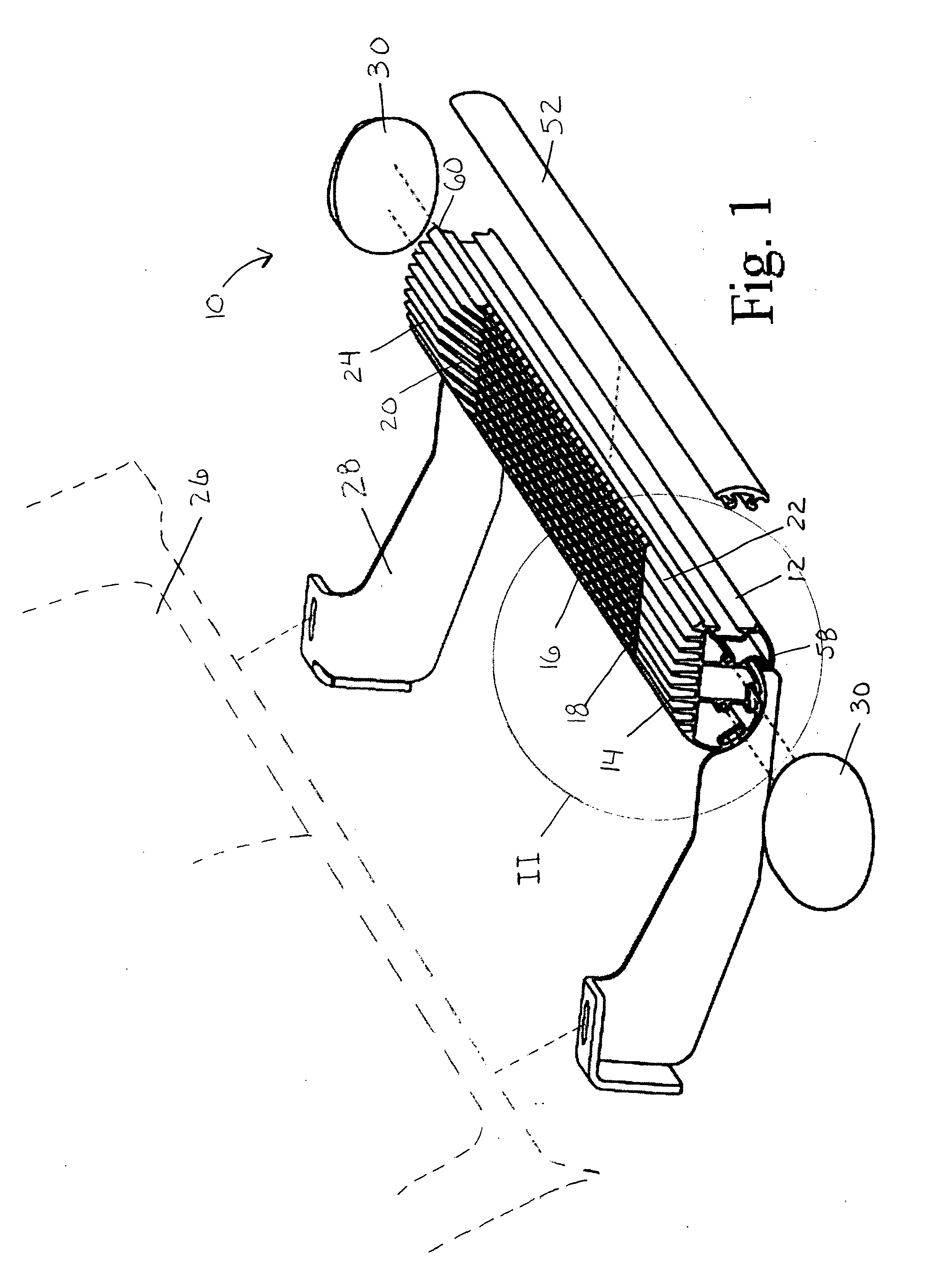
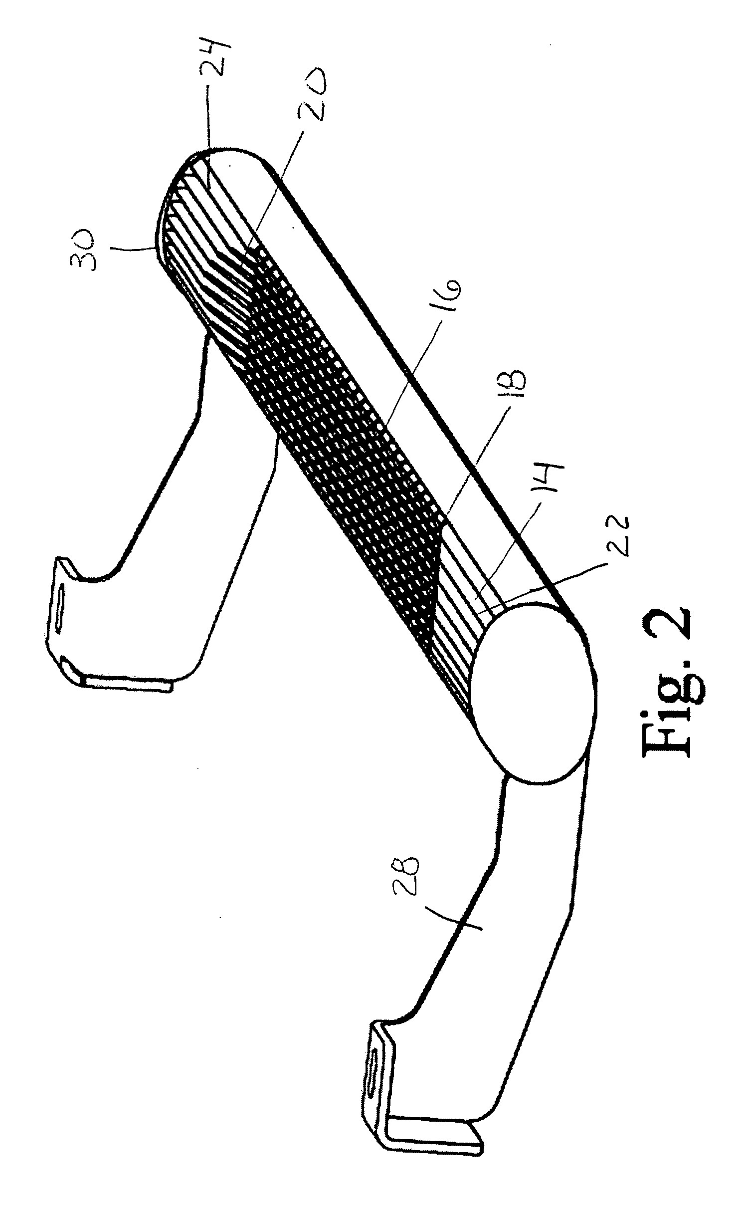
[0029] A step tube constructed in accordance with a preferred embodiment of the present invention is shown in FIGS. 1 and 2 and generally designated 10. The step tube 10 generally includes an elongated extrusion 12, having a plurality of generally vertical ribs 14. The extrusion further includes a step portion 16, transition portions 18, 20 flanking the step portion 16, and non-step portions 22, 24. The step tube is attached to a vehicle 26 with a plurality of mounting brackets 28, and may include a pair of end caps 30.

[0030] As shown in FIG. 3, the extrusion 12 is an elongated beam. The extrusion may be comprised of aluminum, a similar alloy, a thermoplastic, or any other suitable material. As the beam 12 is extruded, it is cut to a desired length, depending on the vehicle that it will be attached to. As shown in FIGS. 1 and 2, the beam 12 includes a step portion 16, transition portions 18, 20 on either side of the step portion 16, and opposing non-step portions 22, 24 adjacent to...


PUM


Abstract

A vehicle step tube comprising a one-piece elongated extrusion having a plurality of vertical ribs extending from the upper surface. The ribs are relatively short in a step portion of the extrusion to form a step platform. The ribs are relatively tall in the non-step portions flanking the step portion. The ribs define transverse recesses in the step portion to enhance traction and aesthetics.

Description

BACKGROUND OF THE INVENTION [0001] The present invention relates to step tubes for vehicles and to a method for making step tubes. [0002] Step tubes, which are substitutes for running boards, are commonly mounted on vehicles for assisting a user of the vehicle to climb into and out of the vehicle. They are also commonly used for aesthetic reasons, and to protect the side of the vehicle. [0003] Step tubes can be fabricated from aluminum extrusions. An example of such a step tube is disclosed in U.S. Pat. No. 6,588,782 to Coomber. The Coomber step tube includes an elongated support portion 100, multiple cap portions 200, a step pad 300, and a mounting bracket 400. The cap portions 200 and the step portion 300 attach to the support portion 100 to form an upper surface of the assembly that is aesthetically pleasing and functional for assisting vehicle users. The step portion 300 may include a name plate 962, a plurality of perforations 964 to allow passage of light through the step pad ...

Claims


Application Information

Patent Timeline
IPC IPC(8): A24C5/18B60R3/00
CPCB60R3/002B60R3/00
Inventor MULDER, CRAIG C.
Owner STEFFENS ENTERPRISES
Why Eureka
Try Eureka