

Inkjet printer
a printer and inkjet technology, applied in the field of inkjet printers, can solve the problems of affecting the direction of ink ejection and deteriorating printing quality
- Summary
- Abstract
- Description
- Claims
- Application Information
AI Technical Summary
Benefits of technology
Problems solved by technology
Method used
Image

Examples
first embodiment
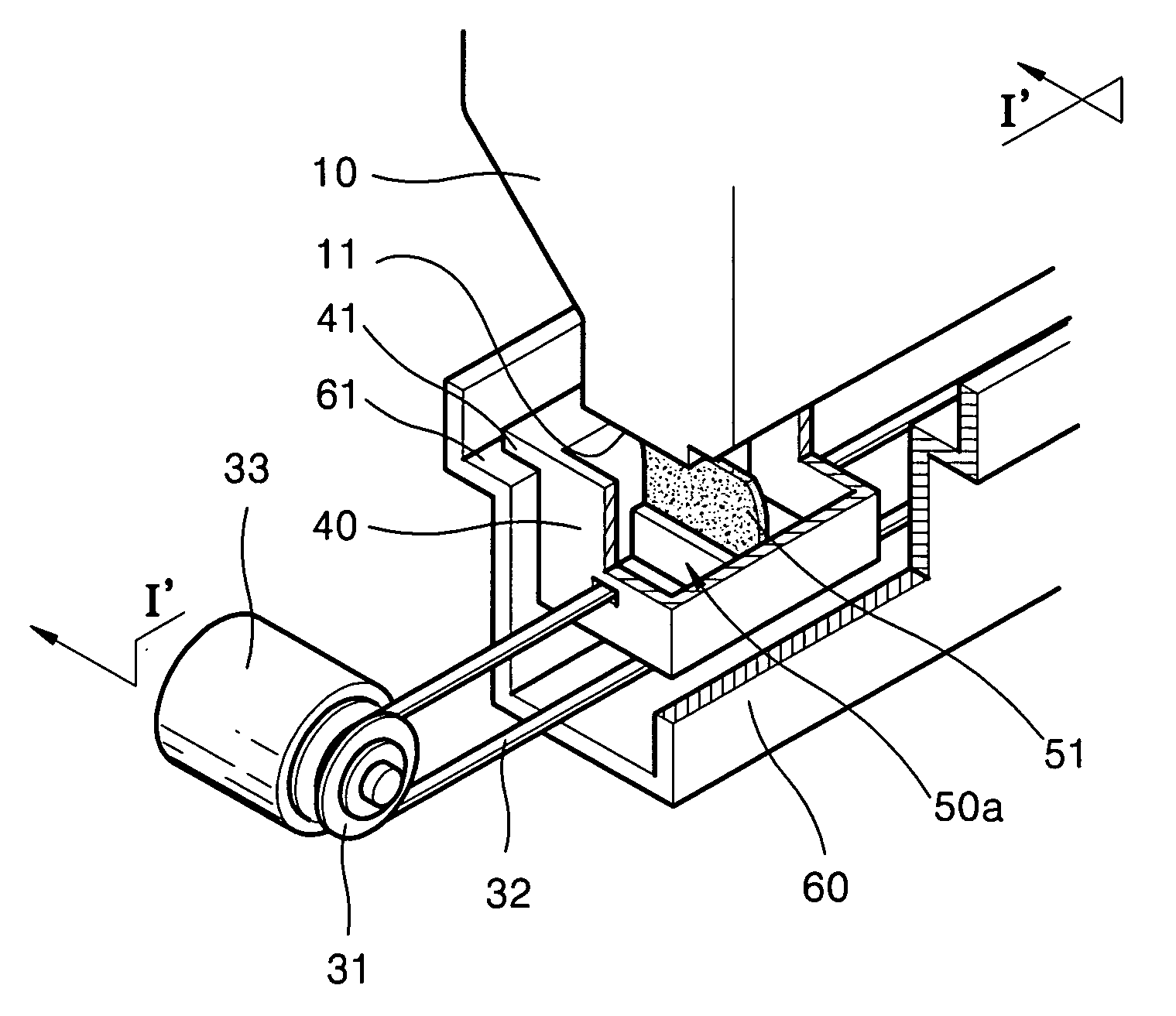
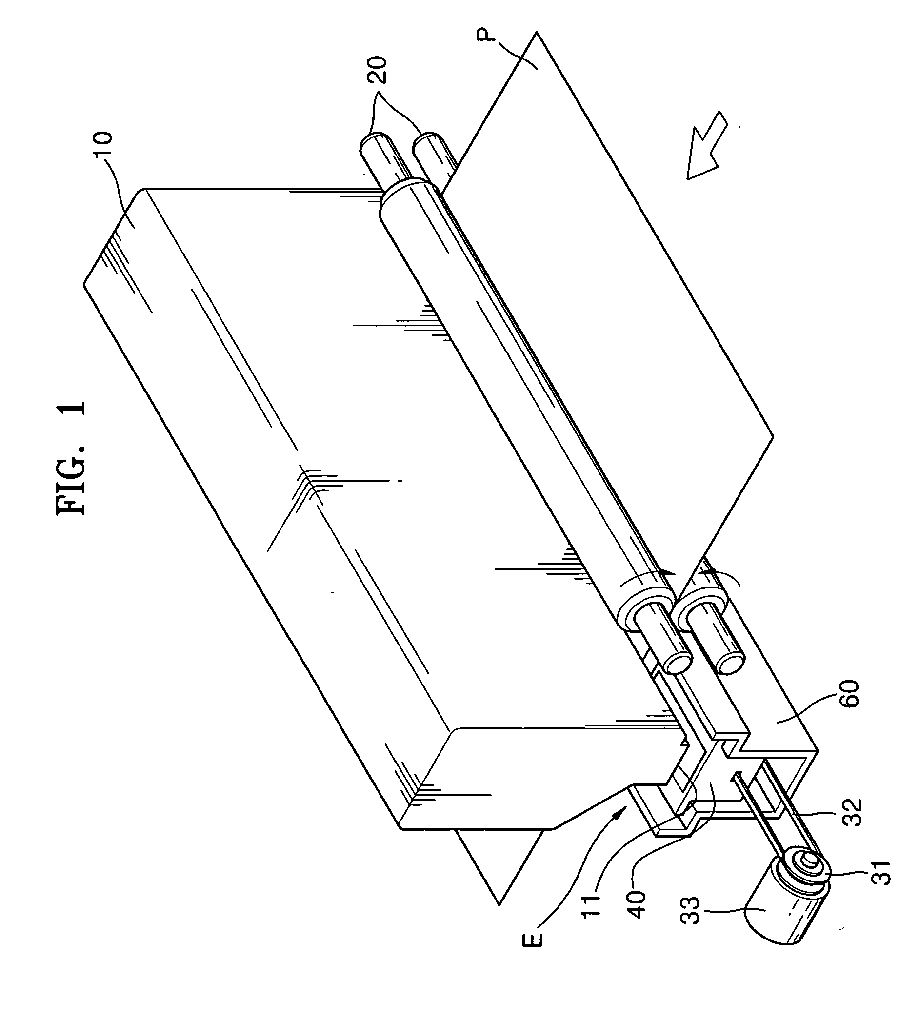
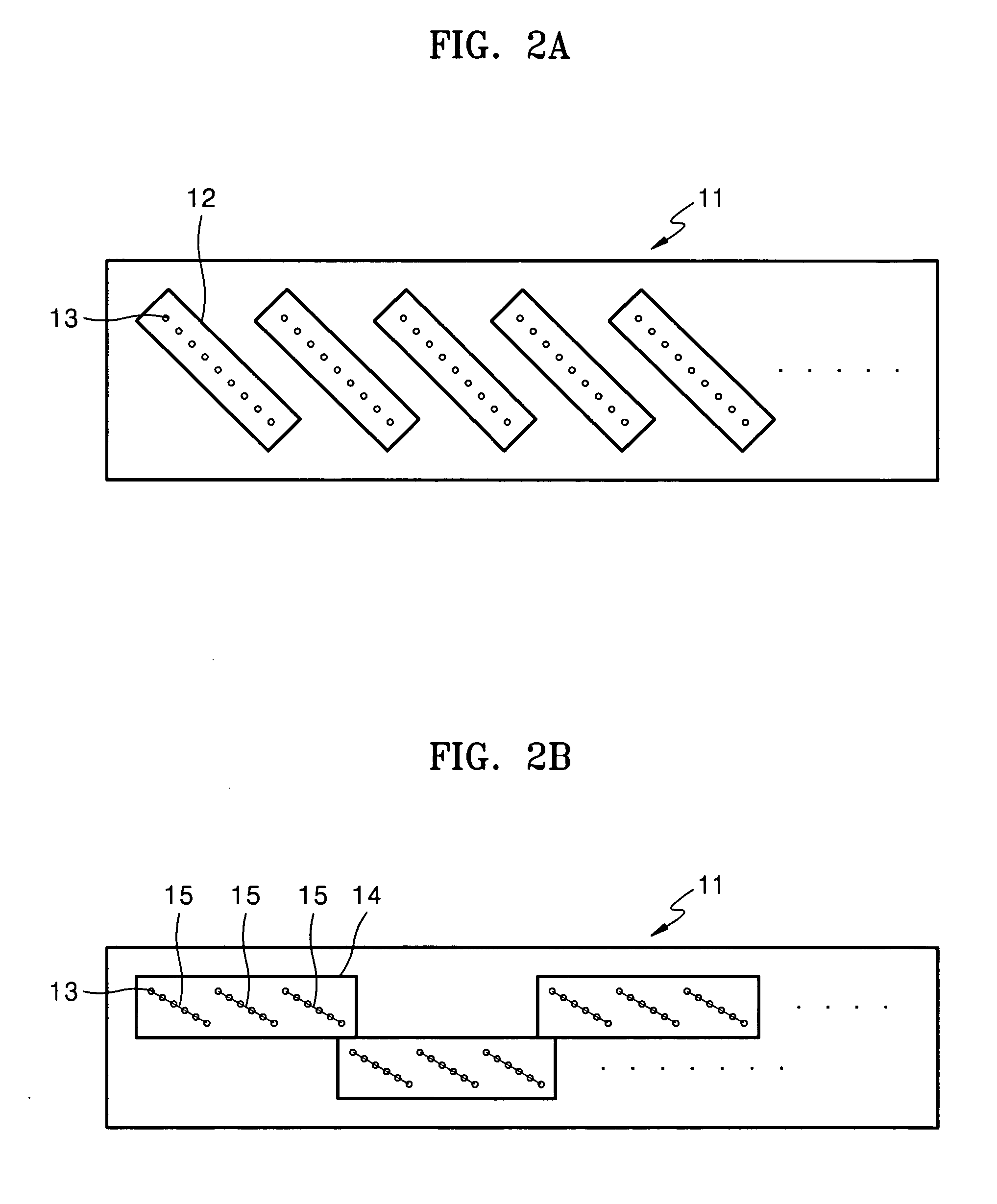
[0034]FIG. 1 is a perspective view of an inkjet printer in accordance with the present invention. Referring to FIG. 1, a paper sheet P is transferred by a pair of rollers 20. The pair of rollers 20 are rotatably engaged with one other. A printhead 10 is placed above paper sheet P. The printhead 10 includes a nozzle portion 11 having a length corresponding to a width of the paper sheet P. FIGS. 2A, 2B, 3A and 3B are are exemplary embodiments of the nozzle portion 11; however, alternative suitable arrangements and constructions may be used. In nozzle portion 11 illustrated in FIG. 2A, nozzle plates 12 have a plurality of nozzles 13 linearly formed thereon which are inclined and arranged in a longitudinal direction of the nozzle portion. In the nozzle portion 11 illustrated in FIG. 2B, nozzle plates 14 have a plurality of rows of nozzles 15 obliquely formed thereon and are arranged in two rows in an alternating fashion. The nozzle portions illustrated in FIGS. 3A and 3B include four ro...
second embodiment
[0038]FIG. 6 is a perspective view of the inkjet printer in accordance with the present invention. FIG. 7 is a sectional view taken along line II′-II′ of FIG. 6. Referring to FIGS. 6 and 7, a cleaning unit 50b includes a plurality of blades 51 arranged radially. The cleaning unit 50b rotates in a longitudinal direction of nozzle portion 11. The cleaning unit 50b is provided with pinions 59 which are engaged with rack gears 62 formed on housing 60. Accordingly, when the drive motor 33 is rotated, moving block 40 moves in a longitudinal direction of the nozzle portion 11. Here, the cleaning unit 50b rotates in the direction of arrow A. Then, a plurality of blades 51 elastically contact the nozzle portion 11 and clean waste ink residing on the nozzle portion 11.
[0039] When the moving block 40 is moved once along a length direction of the nozzle portion 11, the nozzle portion 11 is wiped several times. Referring to FIG. 8, a length L1 of the blade 51 is longer than a distance L2 from th...
third embodiment
[0041]FIG. 11 is a sectional view of an inkjet printer in accordance with the present invention. Referring to FIG. 11, a nozzle portion 11 includes four rows of nozzle sections 11-1, 11-2, 11-3 and 11-4 as illustrated in FIGS. 3A and 3B. A cleaning unit 50c includes four rows of blades 51-1, 51-2, 51-3 and 51-4 which contact the nozzle sections 11-1, 11-2, 11-3 and 11-4, respectively. Accordingly, when moving block 40 moves along in a longitudinal direction of the nozzle portion 11, the blades 51-1, 51-2, 51-3 and 51-4 clean the nozzle sections 11-1, 11-2, 11-3 and 11-4, respectively.
[0042] The inkjet printer having such structure is effective when each of nozzle sections 11-1, 11-2, 11-3 and 11-4 ejects ink of different colors, such as, cyan, magenta, yellow, and black. Each blade 51-1, 51-2, 51-3 and 51-4 cleans the nozzle sections 11-1, 11-2, 11-3 and 11-4 individually, thus preventing ink of different colors from being mixed. For example, the nozzle sections 11-2 ejecting magent...
PUM
 Abstract
Description
Claims
Application Information