Clip with enhanced gripping arrangement

a technology of enhanced gripping and clip, which is applied in the field of surgical ligation clips, can solve the problems of insecureness in the body tissues, loosening of existing surgical clips, and severe consequences for patients, and achieves the effect of enhancing the gripping surfa

Inactive Publication Date: 2005-12-08
MICROLINE PENTAX
View PDF15 Cites 193 Cited by
  • Summary
  • Abstract
  • Description
  • Claims
  • Application Information

AI Technical Summary

Benefits of technology

[0008] It is a feature of the present invention to provide a clip, for example, a surgical clip utilized to hold and secure body tissue. The surgica

Problems solved by technology

Unfortunately, existing surgical clips have been known to loosen and become insecure in the

Method used


Image

  • Clip with enhanced gripping arrangement
  • Clip with enhanced gripping arrangement
  • Clip with enhanced gripping arrangement

Examples


first embodiment

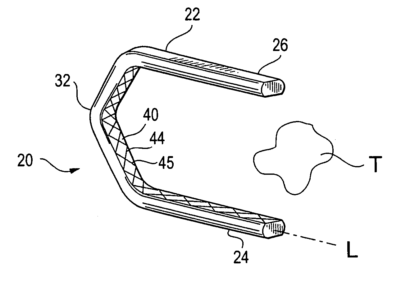
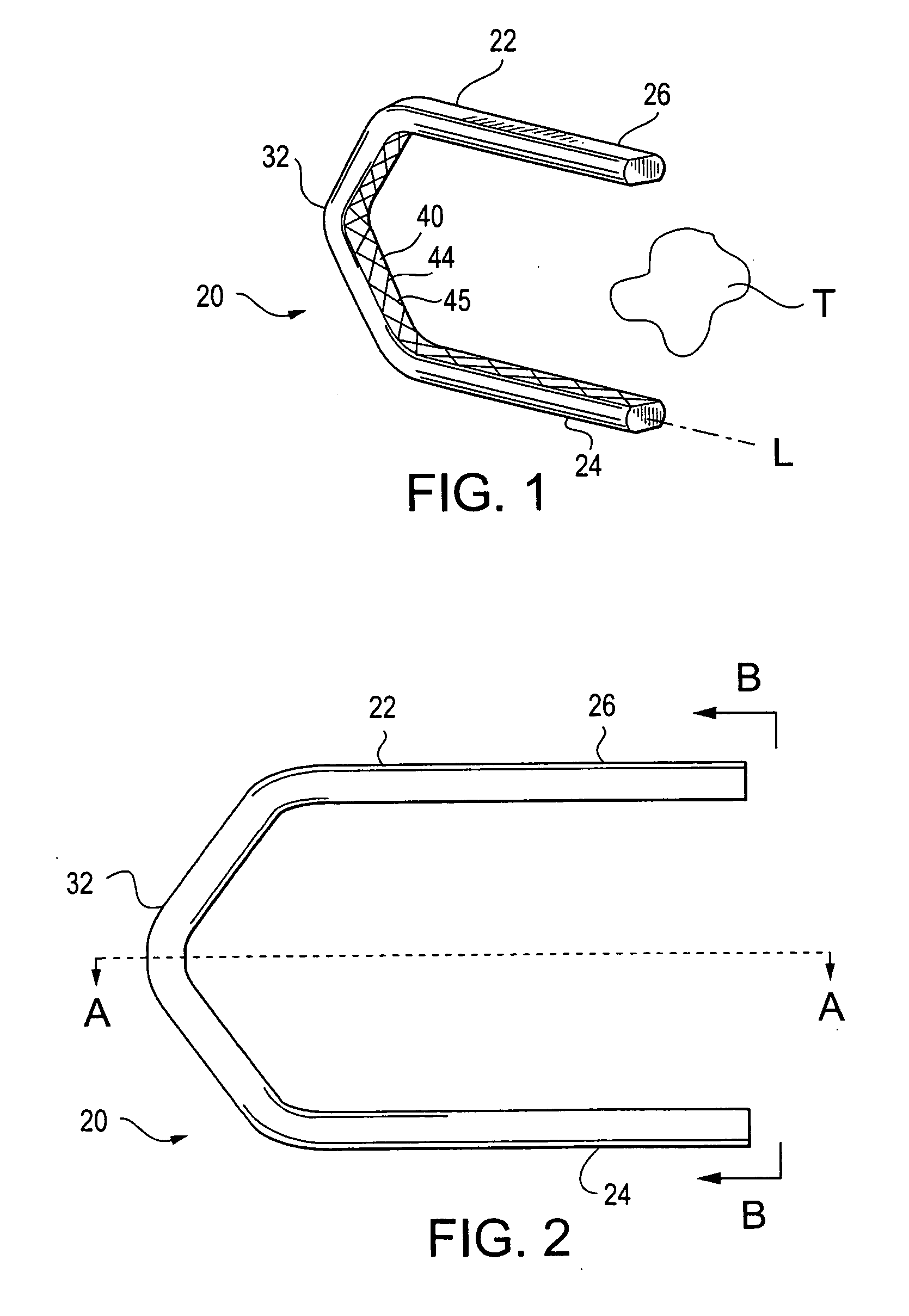
[0034]FIG. 1 shows a perspective view of a surgical clip, according to the present invention. The surgical clip 20 is provided to hold and secure body tissues “T”, including but not limited to the variety of tissues discussed above. An exemplary surgical clip of the present invention may be approximately one-quarter to one-half centimeter in length, although other lengths are possible, depending upon the specific application.

[0035]FIG. 2 is a plan view of the surgical clip shown in FIG. 1, according to an aspect of the present invention. Referring to FIGS. 1 and 2, the surgical clip 20 is formed from a generally U-shaped wire 22 having a pair of legs 24 and 26, each of which extends from one end of a generally V-shaped bridging (i.e., connecting) portion 32. Thus, the surgical clip 20 is open at a first end and closed, or connected, at a second end by the bridging portion 32.

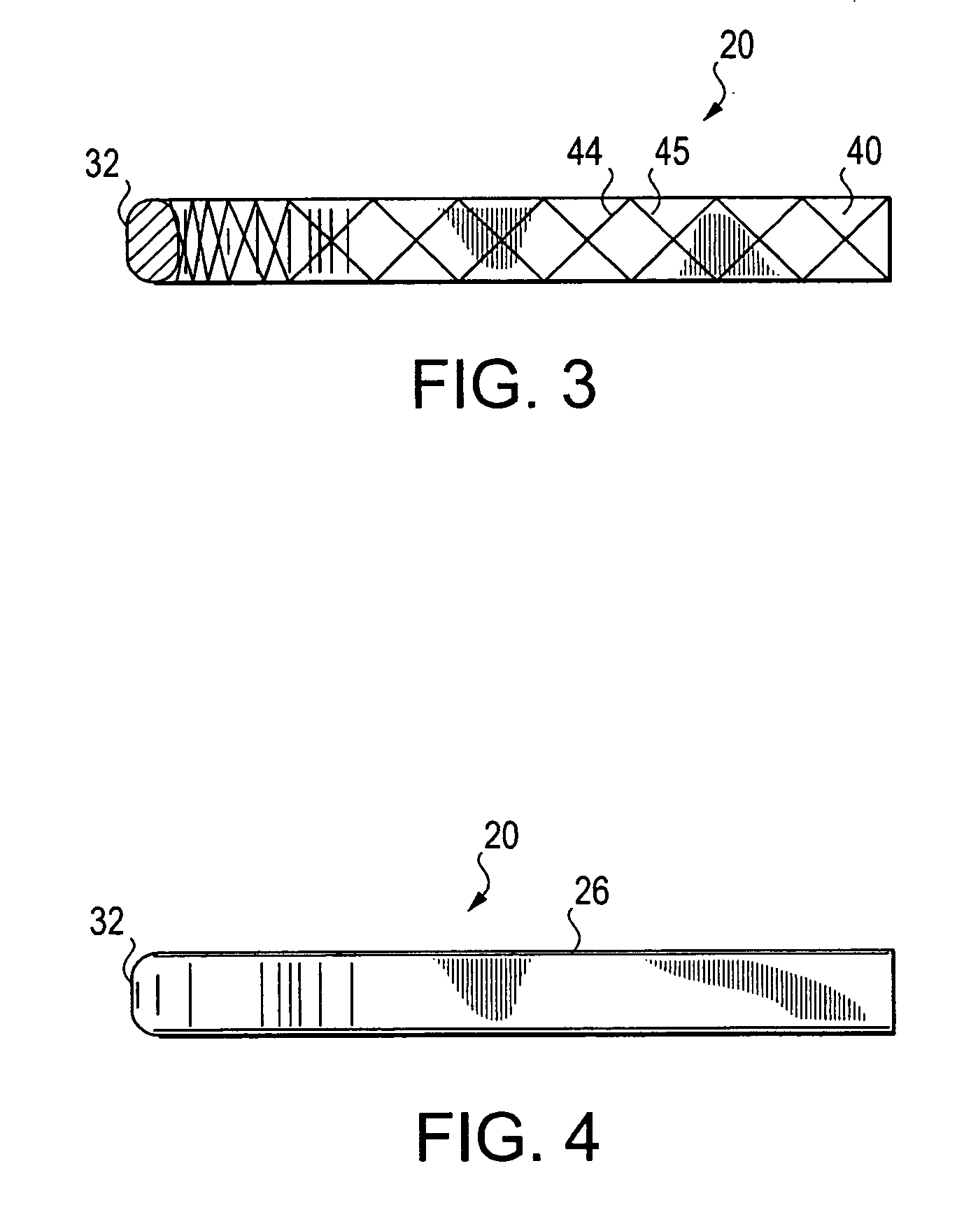
[0036] The wire 22 forming the legs 24 and 26 is generally rectangular in cross-section as shown, for exampl...

second embodiment

[0044]FIG. 8 is a perspective view of a leg section of the surgical clip having a knurl thereon, according to the present invention. As shown the leg 24 includes a generally diamond-like pattern of tissue engaging surfaces 46, which are formed on the inner surface of the surgical clip. The tissue engaging surfaces, similar to gripping knurls, providing additional strength and surgical clip security, without causing any additional tissue trauma. In addition, parallel and perpendicular comparative pull-of tests have demonstrated that the generally diamond-like pattern of tissue engaging surfaces 46 improve the overall gripping and occlusion forces without damaging tissue surfaces, over conventional surgical clip designs.

third embodiment

[0045]FIG. 9 is a perspective view of a knurled pattern on a leg portion of the surgical clip, of the present invention. As shown, the diamond-like pattern of tissue engaging surfaces 46 are more shallow than the diamond-like pattern of tissue engaging surfaces of FIG. 8. Further, the diamond-like pattern of tissue engaging surfaces 46 of FIG. 9 contain broader face surfaces than the diamond-like pattern of tissue engaging surfaces of FIG. 8. In any event, certain variations may be made to the exact shape of the diamond-like pattern of tissue engaging surfaces without departing from the spirit of the present invention.


PUM


Abstract

A surgical clip includes a connecting member having a two ends and a pair of legs. Each leg extends from one end of the connecting member. A generally diamond-shaped pattern is formed on a portion of the inner surface of at least one of the connecting member and the pair of legs. The generally diamond-shaped pattern is formed as the result of generally perpendicular diagonal grooves.

Description

CROSS-REFERENCE TO RELATED APPLICATION [0001] This application claims the benefit of U.S. Provisional Application No. 60 / 576,332 filed on Jun. 2, 2004, the disclosure of which is expressly incorporated by reference in its entirety.BACKGROUND OF THE INVENTION [0002] 1. Field of the Invention [0003] This invention relates generally to surgical ligation clips for securing body tissues, in which the surgical ligation clips have enhanced gripping properties. The disclosure of U.S. patent application Ser. No. 29 / 206,622 filed on Jun. 1, 2004 is expressly incorporated by reference in its entirety. [0004] 2. Description of Background Information [0005] Surgical clips are utilized in surgical procedures to bind tissue together, for instance, to close body tissues or to hold body tissues in place for a period of time. [0006] It is imperative that surgical clips remain in place and do not move in an undesirable manner, fall out, or otherwise become loose. Existing surgical clips utilized today...

Claims


Application Information

Patent Timeline
IPC IPC(8): A61B17/00A61B17/12A61B17/122
CPCA61B17/122A61B2017/00858A61B17/12
Inventor THEROUX, MARCMENN, PAVELTATTERFIELD, WILLIAM
Owner MICROLINE PENTAX
Why Eureka
Try Eureka