Packaging for modified atmosphere packaging and method

a technology of modified atmosphere and packaging, applied in the field of packaging for modified atmosphere, can solve the problems that the horizontal flange of the cardboard tray folded out of an unfolded sheet cannot have rounded corners, limit the design freedom of the appearance of such prior art packaging, etc., and achieve the effect of facilitating the positioning of the plastic flange and substantially increasing the ripping surfa

Active Publication Date: 2022-04-19
PEKEBL BV
View PDF18 Cites 0 Cited by
  • Summary
  • Abstract
  • Description
  • Claims
  • Application Information

AI Technical Summary

Benefits of technology

[0034]When the plastic barrier foil is first fixed to the plastic flange, the gripping surface is substantially increased allowing for a easier positioning of the plastic flange into the mold onto the upper edge of the peripheral wall.
[0035]Furthermore, when the already fixed plastic barrier foil is heated again to be pushed into the formed cardboard tray, the edge of the plastic barrier foil can be sealed to the second part of the plastic flange providing a firm connection between the plastic barrier foil and the plastic flange. It also prevents a user, after a closing foil is arranged on the packaging, from pulling the wrong layer of foil, when trying to open the packaging.

Problems solved by technology

However, a cardboard tray with a horizontal flange folded out of an unfolded sheet cannot have rounded corners.
This thus limits the design freedom of the appearance of such prior art packaging.

Method used


Image

  • Packaging for modified atmosphere packaging and method
  • Packaging for modified atmosphere packaging and method
  • Packaging for modified atmosphere packaging and method

Examples


Embodiment Construction

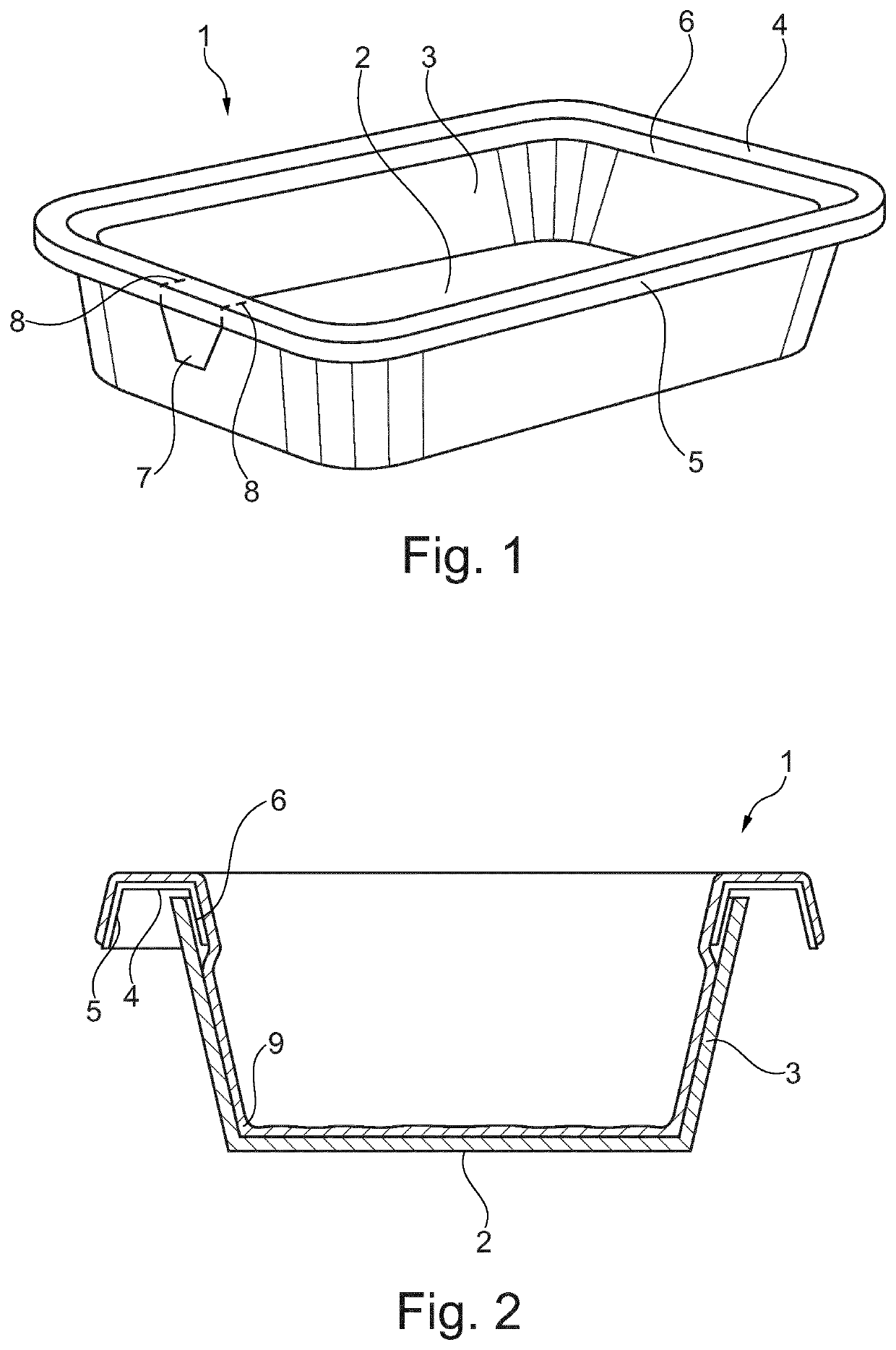
[0048]FIG. 1 shows a perspective view of a packaging 1 according to the invention. The packaging 1 has a bottom 2 and a peripheral wall 3 out of cardboard. The bottom 2 and the peripheral wall 3 have rounded corners.

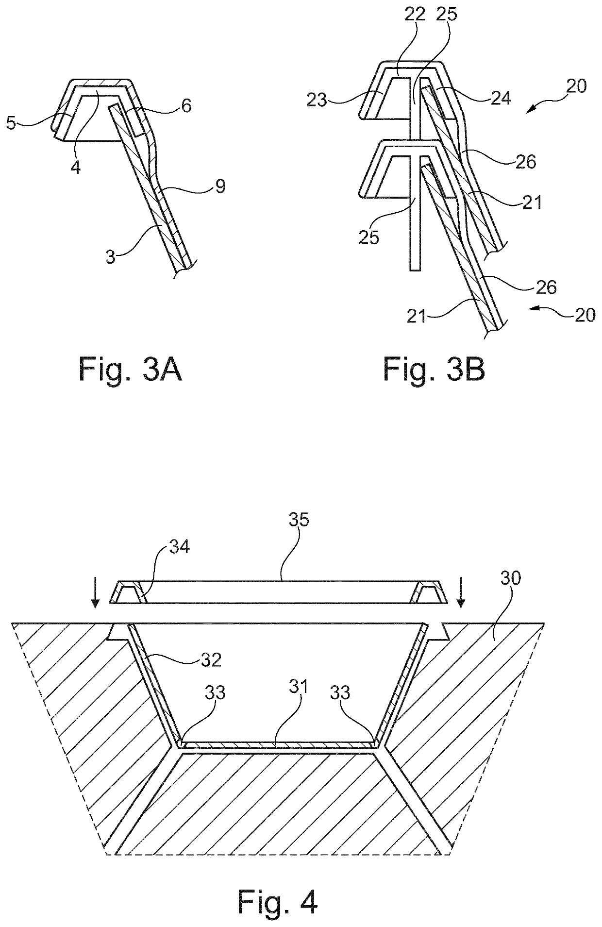
[0049]A plastic flange 4, 5, 6 is arranged on top of and in direct contact with the upper edge of the peripheral wall 3. The plastic flange has a horizontal first part 4, a second part 5 depending downward along the outside of the peripheral wall 3 and a third part 6 depending downward along the inside of the peripheral wall 3.

[0050]A tear lip 7 is provided on the outside of the plastic flange 4, 5, 6 and perforation lines 8 are provided in the first part 4, the second part 5 and the third part 6 of the plastic flange. With tear lip 7 a user can tear loose a part of the plastic flange 4, 5, 6 such that the plastic flange 4, 5, 6 can be separated easier from the cardboard 2, 3.

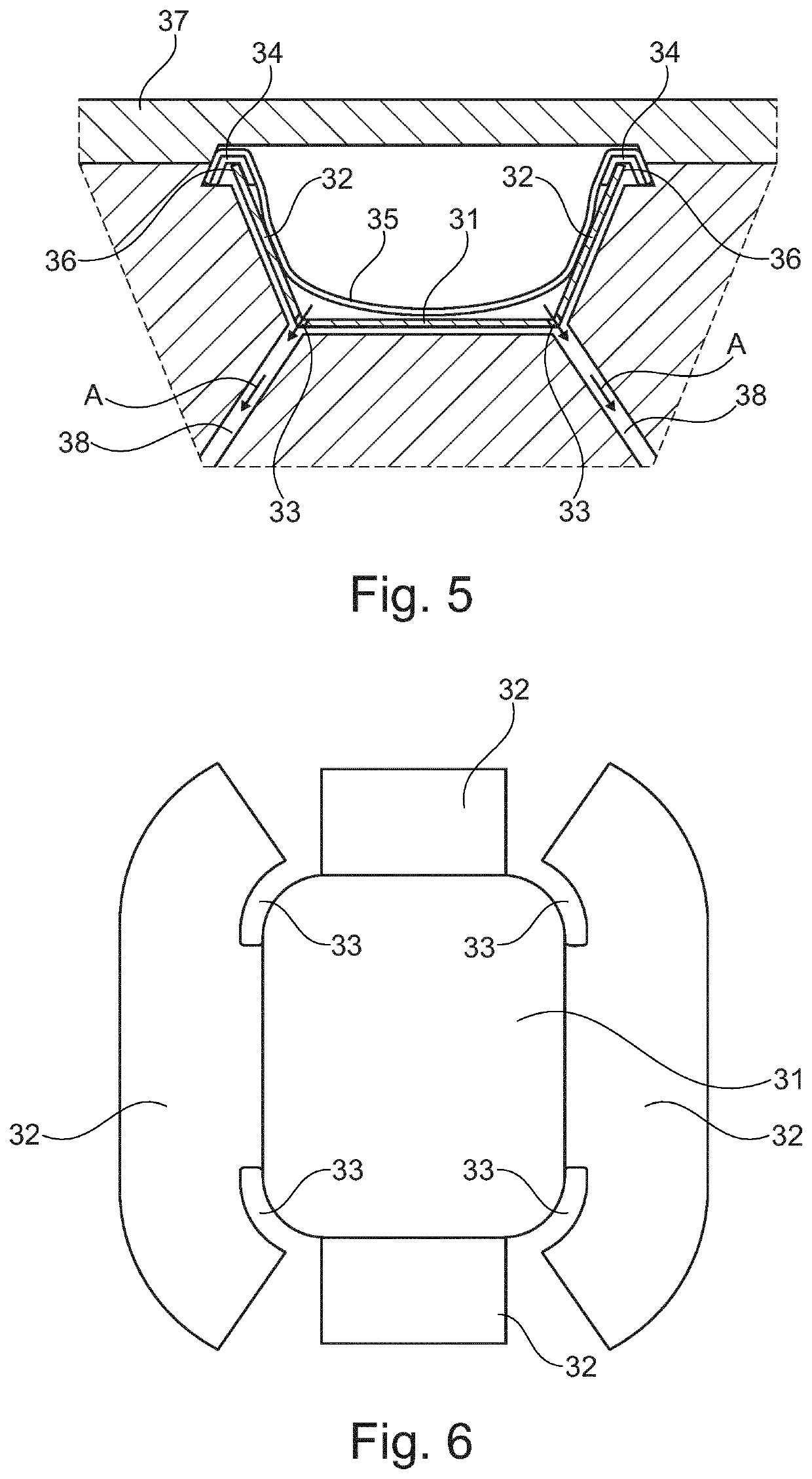
[0051]FIG. 2 shows a cross-sectional view of the packaging 1 from which it is more clear that th...


PUM

PropertyMeasurementUnit
widthaaaaaaaaaa
pressureaaaaaaaaaa
shapeaaaaaaaaaa

Abstract

A packaging for modified atmosphere packaging includes a flangeless cardboard tray having a bottom and an upstanding peripheral wall. A plastic flange is arranged on top of the edge of the peripheral wall. The plastic flange has in cross-section a first part extending horizontally, substantially parallel to the bottom of the tray, a second part depending from the first part downward along the outside of the peripheral wall and a third part depending from the first part, opposite of the second part, along the inside of the peripheral wall. A plastic barrier foil is adhered to and lines the inside of the cardboard tray and extends over the plastic flange to fix the plastic flange onto the flangeless cardboard tray.

Description

CROSS-REFERENCE TO RELATED APPLICATIONS[0001]This application is the United States national phase of International Application No. PCT / EP2017 / 074996 filed Oct. 2, 2017, and claims priority to European Patent Application No. 16200964.1 filed Nov. 28, 2016, the disclosures of which are hereby incorporated by reference in their entirety.BACKGROUND OF THE INVENTIONField of the Invention[0002]The invention relates to a packaging for modified atmosphere packaging. Such a packaging is for example known from EP 2726380.Description of Related Art[0003]EP 2726380 discloses a packaging, wherein first a cardboard tray is formed out of an unfolded sheet, wherein the cardboard tray has at the upper edge of the peripheral wall a horizontal flange. Over this flange, a separate plastic flange with a horizontal part and a part depending downward on the outside of the flange of the tray is positioned. Then a plastic barrier foil is arranged in the tray by vacuum, such that the plastic barrier foil lin...

Claims


Application Information

Patent Timeline
Patent Type & Authority Patents(United States)
IPC IPC(8): B65D5/60B31B50/44B29C65/02B29C65/00B65D21/02B65D77/20B31B120/40B31B105/00B31B110/35B31B120/00B29L31/00B29C45/14B29C39/02B29C45/16
CPCB65D5/60B29C65/02B29C66/7486B31B50/44B65D21/0233B65D77/2024B29C39/02B29C45/14B29C45/16B29L2031/712B31B2105/0024B31B2110/35B31B2120/002B31B2120/404B65D5/603B29C65/5042B29C65/76B29C66/1122B29C66/534B29C66/5344B29C63/30B65D15/04B65D25/16B31B2110/10B29C65/00
Inventor ZWAGA, RONALD
Owner PEKEBL BV
Why Eureka
Try Eureka