Wireless danger proximity warning system and method
a proximity warning and wireless technology, applied in traffic control systems, transportation and packaging, instruments, etc., can solve the problems of 200,000 passive railroad crossings, inability to detect danger,
- Summary
- Abstract
- Description
- Claims
- Application Information
AI Technical Summary
Problems solved by technology
Method used
Image
Examples
first embodiment
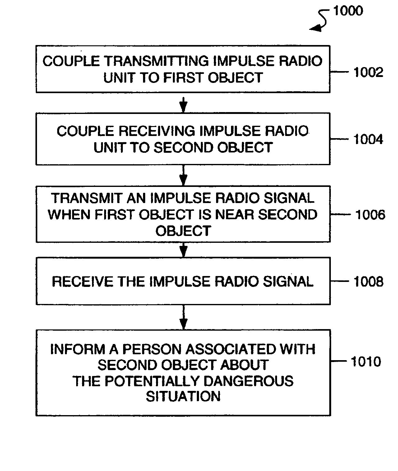
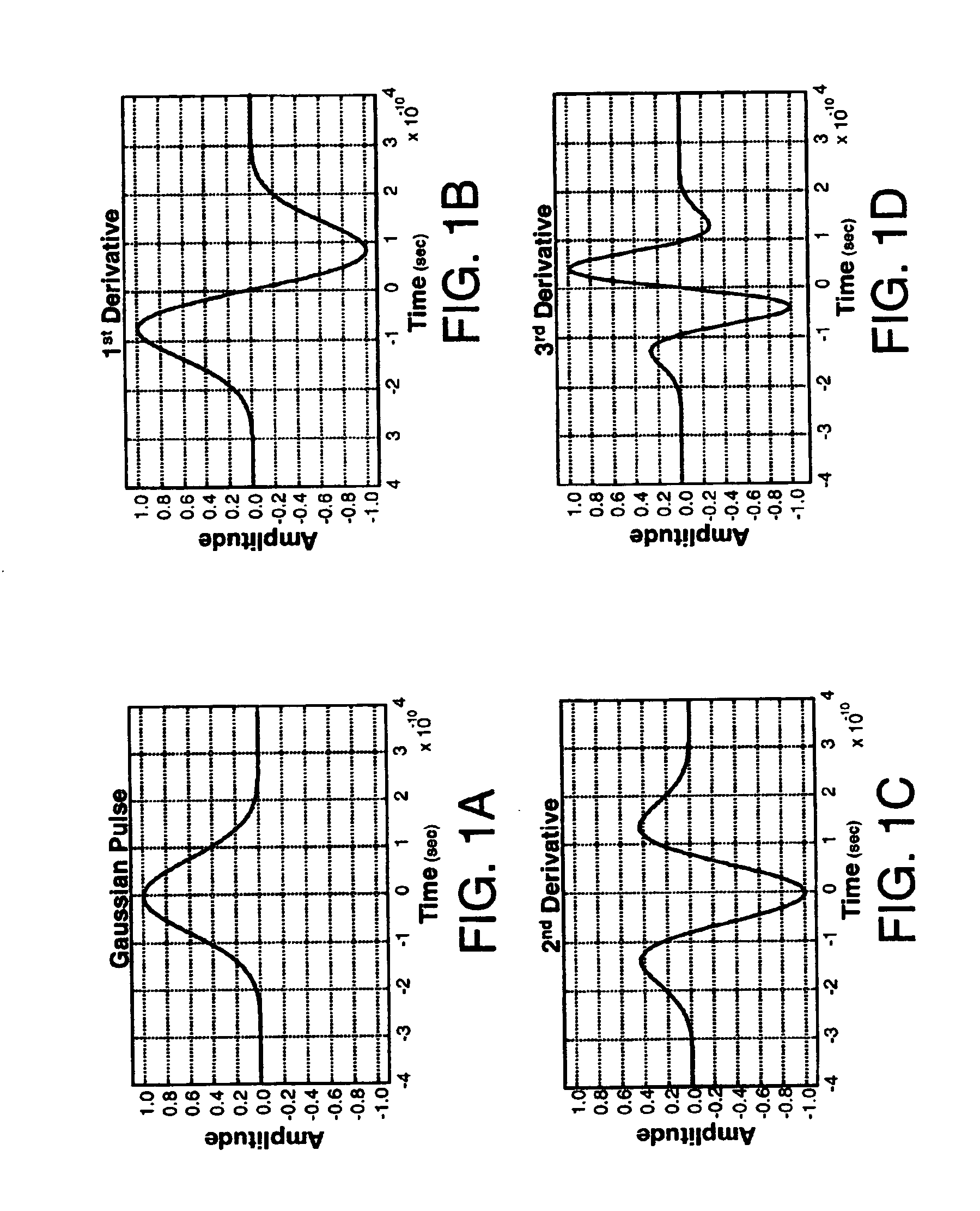
[0140] Referring to FIGS. 11 and 12, there are diagrams illustrating in greater detail the components and steps of the danger proximity warning system 900a and method 1000a. In this embodiment, the danger proximity warning system 900 includes a transmitting impulse radio unit 902 coupled (step 1202) to a first object such as locomotive 1102 and a receiving impulse radio unit 904 coupled (step 1204 ) to a second object such as vehicle 1104 (shown as a car). The transmitting impulse radio unit 902 operates to transmit (step 1206) an impulse radio signal 910 having a known pseudorandom sequence of pulses that look like a series of Gaussian waveforms (see FIGS. 1-3) towards the receiving impulse radio unit 904 attached to the second object (e.g., vehicle 1104). In particular, the transmitting impulse radio unit 902 may continually transmit the impulse radio signal 910 or it may transmit the impulse radio signal 910 whenever an alert condition is met such as when a whistle on the locomot...
second embodiment
[0143] Referring to FIGS. 13 and 14, there are diagrams illustrating in greater detail the components and steps of the danger proximity warning system 900b and method 1000b. In this embodiment, the danger proximity warning system 900b includes a transmitting impulse radio unit 902 coupled (step 1402) to a first object such as locomotive 1102 and a receiving impulse radio unit 904 coupled (step 1404) to a second object such as an active railroad pole 1302. The transmitting impulse radio unit 902 operates to transmit (step 1406) an impulse radio signal 910 having a known pseudorandom sequence of pulses that look like a series of Gaussian waveforms (see FIGS. 1-3) towards the receiving impulse radio unit 904 attached to the second object (e.g., railroad pole 1302 of which two are shown). In particular, the transmitting impulse radio unit 902 may continually transmit the impulse radio signal 910 or it may transmit the impulse radio signal 910 whenever a alert condition is met such as wh...
third embodiment
[0146] Referring to FIGS. 15 and 16, there are diagrams illustrating in greater detail the components and steps of the danger proximity warning system 900c and method 1000c. In this embodiment, the danger proximity warning system 900c includes a transmitting impulse radio unit 902 coupled (step 1602) to a first object such as control box 1502 and a receiving impulse radio unit 904 coupled (step 1604) to a second object such as vehicle 1104. The control box 1502 is located in a monitoring location such as next to railroad tracks 1504 and is capable of using a sensor 1506 (e.g., electromagnetic sensor, motion detector, percussion sensor) to sense the presence of a third object (e.g., locomotive 1102). Moreover, the control box 1502 can be powered by a variety of power sources including, for example, a solar battery or a power line.
[0147] The transmitting impulse radio unit 902 operates to transmit an impulse radio signal 910 having a known pseudorandom sequence of pulses that look lik...
PUM
 Abstract
Description
Claims
Application Information
 - R&D
- Intellectual Property
- Life Sciences
- Materials
- Tech Scout
- Unparalleled Data Quality
- Higher Quality Content
- 60% Fewer Hallucinations
Browse by: Latest US Patents, China's latest patents, Technical Efficacy Thesaurus, Application Domain, Technology Topic, Popular Technical Reports.
© 2025 PatSnap. All rights reserved.Legal|Privacy policy|Modern Slavery Act Transparency Statement|Sitemap|About US| Contact US: help@patsnap.com


