Methods and apparatus for providing and distributing standby power

a technology of standby power and method, applied in the direction of power network operation system integration, process and machine control, emergency power supply arrangement, etc., can solve the problems of difficult communication among the components, if possible at all, and high cost of generator installation in the facility power system

Active Publication Date: 2005-12-15
AMERICA POWER CONVERSION CORP
View PDF25 Cites 94 Cited by
  • Summary
  • Abstract
  • Description
  • Claims
  • Application Information

AI Technical Summary

Benefits of technology

[0011] The power distribution system may further include a plurality of circuit breakers mounted in the enclosure and operatively coupled between the first controlled switch and the second controlled switch and the at least one output, and may also include a plurality of bus bars bolted to each of the first controlled switch and the second controlled switch. The system may further include a user interface device coupled to the controller. The enclosure may include a front door, and the user interface device may be mounted in the enclosure and accessible through an opening in the front door of the enclosure. The enclosure may include an inner panel, accessible with the front door in an open position, having at least one opening to allow access to the first controlled switch and the second controlled switch. The user interface device may be mounted to the inner panel. The controller may be configured to control the first switch and the second switch to provide an electrical interlock. The enclosure may have an input to receive a DC voltage from a generator, and the controller may be configured to be powered from the DC voltage. The system may further include a removable panel coupled to the enclosure, wherein the first controlled switch and the second controlled switch are mounted to the panel. The removable panel may have a handle mounted to a top section of the removable panel, and a pair of wheels mounted to a bottom section of the removable panel.
[0012] Yet another aspect of the invention is directed to a system for providing control of power to a plurality of devices in a facility. The system includes a facility controller, a power distribution device having a first input to receive power from a utility power source, a second input to receive power from a backup power source and an output that provides power from at least one of the utility power source and the backup power source, and an uninterruptible power supply coupled to the output of the power distribution device and configured to provide output power derived from one of the utility power source, the backup power source, and a battery power source. The facility controller is configured to receive operational data related to status of the utility power source, the backup power source, and the uninterruptible power supply, and to control distribution of power to the plurality of devices based on the operational data received.
[0013] The system may further include a controllable power switch operatively coupled to the facility controller and to the output of the power distribution device, and the controllable power switch may include a plurality of power outlets that are controlled based on signals from the facility controller to implement power shedding based on a detection of a loss of utility power. At least one of the plurality of devices may be an air conditioning unit, and the facility controller may be configured to detect a temperature in the facility and control the air conditioning unit based on the temperature detected and an operational state of the utility power and the backup power source. The backup power source may be a generator, and the power distribution device may include a controller configured to communicate status of the generator and the utility power to the facility controller. The controller of the power distribution device may be configured to determine remaining run time of the generator and communicate data regarding the remaining run time to the facility controller. The power distribution device may further include a first switch operatively coupled to the first input and the output and operative to selectively couple the first input to the output, and a second switch operatively coupled to the second input and the output and operative to selectively couple the second input to the output, and the controller of the power distribution device may be operatively coupled to the first switch and to the second switch and configured to control the first switch and the second switch to provide an electrical interlock. Each of the first switch and the second switch may have an open position and a closed position, and the controller of the power distribution device may be configured to control the first switch to switch from the closed position to the open position, if the second switch is switched from the open position to the closed position. The controller of the power distribution device may also be configured to control the first switch to switch from the closed position to the open position a predetermined period of time after the second switch is switched from the open position to the closed position.

Problems solved by technology

The installation of a generator in a facility power system is typically an expensive ordeal requiring the hiring of an engineering firm along with several subcontractors to design and install the associated control and switching systems needed to integrate the generator into the facility power system.
As a result, each system is a unique system that requires substantial labor in the field in an uncontrolled environment.
Control systems are often designed into facility power systems, however, because different components of the systems may be supplied by different manufacturers, these control systems often use different communication protocols making communication among the components difficult, if possible at all.
One problem with these switches is that they represent a single point of failure in the system.
Upon certain failure conditions of such transfer switches, since the switch is implemented using a single device, the switch is not able to provide power from either the primary source or the back-up source.
In critical facilities, such failures are unacceptable.
Another problem with these switches is that the mechanical interlock typically prevents simultaneous power from being supplied by both the generator and the utility, resulting in a brief power outage when utility power returns and the supply of power is switched from generator to utility.

Method used


Image

  • Methods and apparatus for providing and distributing standby power
  • Methods and apparatus for providing and distributing standby power
  • Methods and apparatus for providing and distributing standby power

Examples


Embodiment Construction

[0037] This invention is not limited in its application to the details of construction and the arrangement of components set forth in the following description or illustrated in the drawings. The invention is capable of other embodiments and examples and of being practiced or of being carried out in various ways. Also, the phraseology and terminology used herein is for the purpose of description and should not be regarded as limiting. The use of “including,”“comprising,” or “having,”“containing”, “involving”, and variations thereof herein, is meant to encompass the items listed thereafter and equivalents thereof as well as additional items.

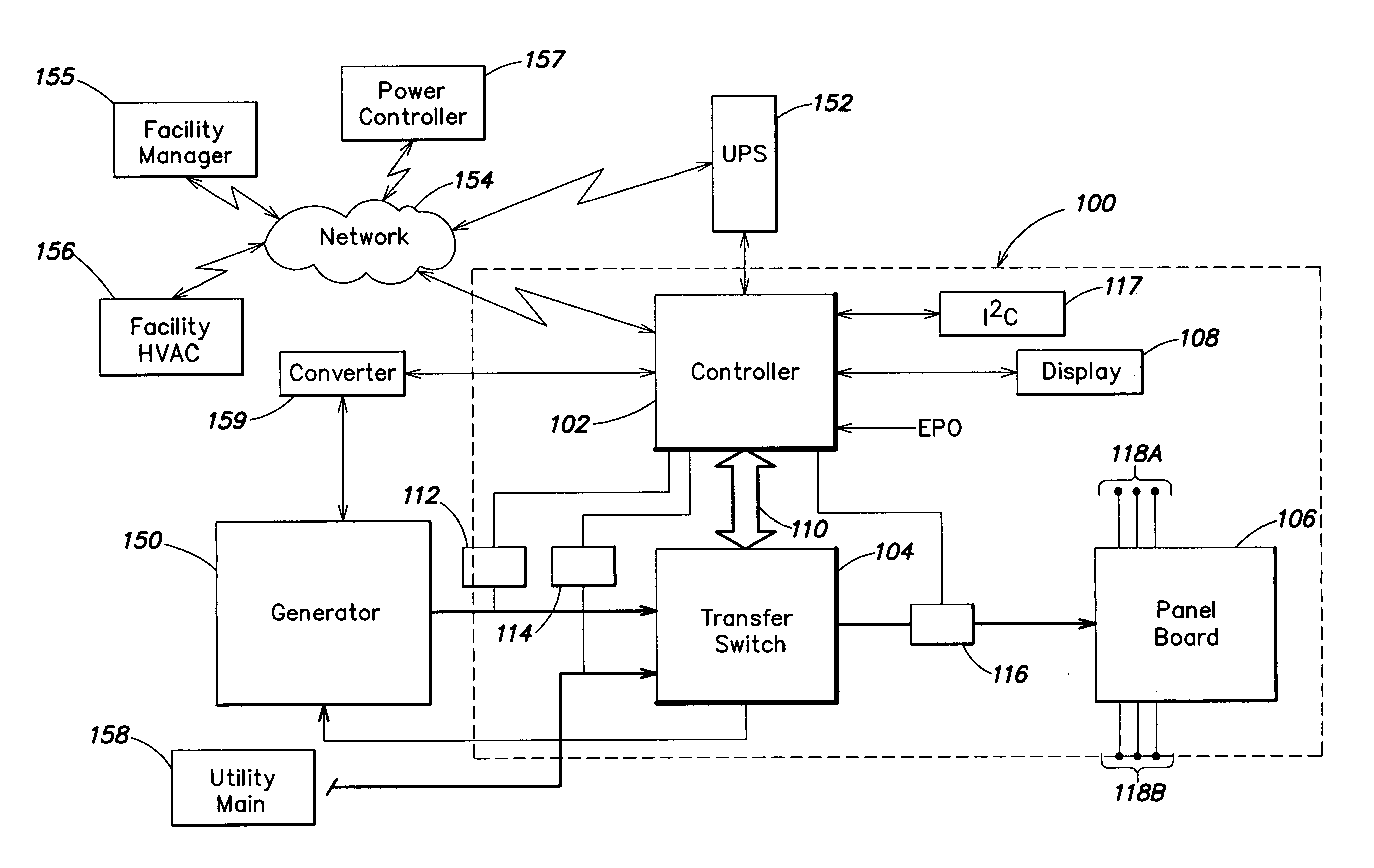
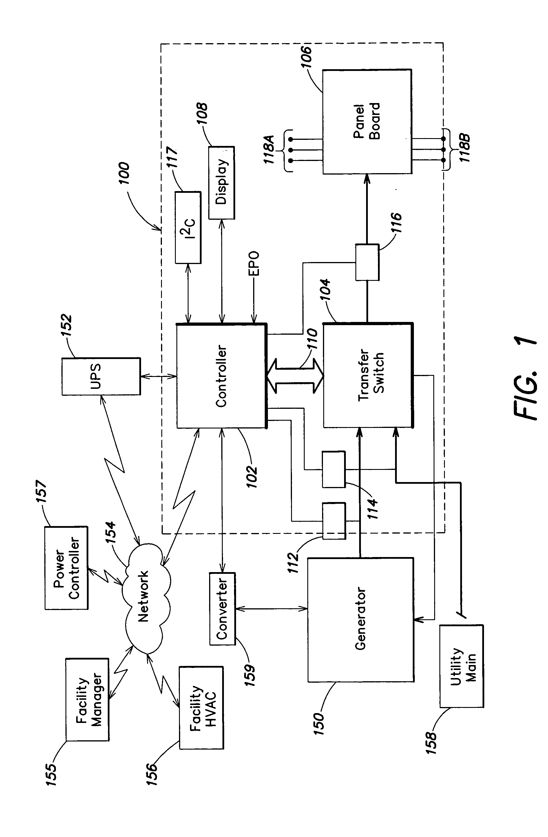
[0038] A system in accordance with one embodiment of the invention for providing, monitoring and distributing power will now be described with reference to FIG. 1, which shows a functional block diagram of a system 100. The system 100 includes a controller 102, a transfer switch 104, a panel board 106, a display 108, a distribution bus 110, an I2...


PUM

PropertyMeasurementUnit
currentaaaaaaaaaa
timeaaaaaaaaaa
timeaaaaaaaaaa

Abstract

Aspects of the invention are directed to power distribution systems and methods for distributing power from a primary power source and a backup power source to a load. In one particular aspect, a power distribution system includes a first input to receive input power from the primary power source, a second input to receive input power from the backup power source, an output that provides output power from at least one of the primary power source and the backup power source, a first switch operatively coupled to the first input and the output and operative to selectively couple the first input to the output, a second switch operatively coupled to the second input and the output and operative to selectively couple the second input to the output, and a controller operatively coupled to the first switch and to the second switch and configured to control the first switch and the second switch to provide an electrical interlock.

Description

BACKGROUND OF INVENTION [0001] 1. Field of Invention [0002] Embodiments of the invention relate generally to methods and apparatus for providing uninterruptible power to sensitive and / or critical loads. More specifically, embodiments of the invention relate to distribution and control systems for power systems having backup power sources. [0003] 2. Discussion of Related Art [0004] The use of uninterruptible power supplies (UPSs) and backup power sources, such as generators, to provide uninterrupted power to critical loads is well known. Typically, UPSs use batteries to provide uninterrupted power during relatively brief power outages, while backup generators are used to provide power during longer power outages. Typically, a UPS is used to provide power for outages less than thirty minutes, but depending on the power draw of a load, and the capacity of batteries used in a UPS, the actual runtime of a UPS may be greater or less than thirty minutes. When longer runtime than that provi...

Claims


Application Information

Patent Timeline
Patent Type & Authority Applications(United States)
IPC IPC(8): H02J9/04H02J9/06H02J9/08
CPCH02J9/06H01H2300/018Y04S20/20Y02B70/30
Inventor RASMUSSEN, NEILZIEGLER, WILLIAMCOLUCCI, DAVID A.
Owner AMERICA POWER CONVERSION CORP
Why Eureka
Try Eureka