Method and apparatus for performing a function in a plant using process performance monitoring with process equipment monitoring and control

a technology of process equipment and process performance, applied in the direction of testing/monitoring control systems, instruments, nuclear elements, etc., can solve the problems of not being directly accessible to other areas of the plant, not necessarily aware of the process controller, and not being available to plant personnel, so as to improve the overall view or state, improve the operation of the process, and improve the diagnosis of problems

Inactive Publication Date: 2007-04-17
FISHER-ROSEMOUNT SYST INC
View PDF363 Cites 321 Cited by
  • Summary
  • Abstract
  • Description
  • Claims
  • Application Information

AI Technical Summary

Benefits of technology

[0013]A process control system includes a data collection and distribution system that collects and stores data from different data sources, each of which may use it own proprietary manner of acquiring or generating the data in the first place. The data collection and distribution system then makes the stored data available to other applications associated with or provided in the process control system or to applications associated with the data sources themselves for use in any desired manner. In this manner, applications may use data from vastly different data sources to provide a better view or insight into the current operational status of a plant, to make better or more complete diagnostic or financial decisions regarding the plant, etc. Thus, applications may be provided which combine or use data from previously disparate collection systems such as process control monitoring systems, equipment monitoring systems and process performance models to determine a better overall view or state of a process control plant, to better diagnose problems and to take or recommend actions in production planning and maintenance within the plant. For example, information or data may be collected by maintenance functions pertaining to the health, variability, performance or utilization of a device, loop, unit, etc. This information may then be sent to and displayed to a process operator or maintenance person to inform that person of a current or future problem. This same information may be used by the process operator to correct a current

Problems solved by technology

In the past however, process controllers were not necessarily aware of these other devices or the process controllers simply assumed that these devices were operating properly when performing process control.
Such optimizers typically use complex models of the plant to predict how inputs may be changed to optimize operation of the plant with respect to some desired optimization variable such as, for example, profit.
In many cases, however, these optimizers are provided by outside service organizations and, thus, are not directly accessible to other areas of the plant.
Because, for the most part, very different applications used to perform the different functions within a plant, e.g., process control operations, maintenance operations and business operations are separated, the different applications used for these different tasks are not integrated and, thus, do not share data or information.
In these cases, the data is typically collected and stored in a proprietary manner and is rarely made available to the plant personnel for other reasons.
Still further, even if all of the applications are located within a plant, because different personnel use these different applications and analysis tools and because these tools are generally located at different hardware locations within the plant, there is little if any flow of information from one functional area of the plant to another, even when this information may be useful to other functions within the plant.
This tool may detect a problem and alert the maintenance person that the device needs to be calibrated, repaired or replaced.
However, the process control operator (either a human or a software ex

Method used


Image

  • Method and apparatus for performing a function in a plant using process performance monitoring with process equipment monitoring and control
  • Method and apparatus for performing a function in a plant using process performance monitoring with process equipment monitoring and control
  • Method and apparatus for performing a function in a plant using process performance monitoring with process equipment monitoring and control

Examples


Embodiment Construction

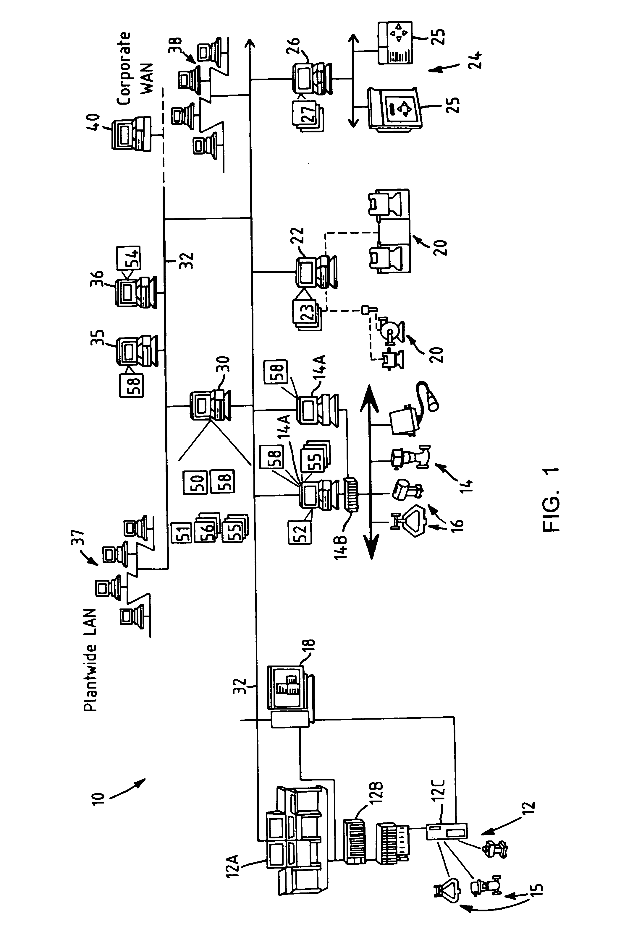
[0032]Referring now to FIG. 1, a typical process control plant 10 includes a number of business and other computer systems interconnected with a number of control and maintenance systems by one or more communication networks. The illustrated process control plant 10 also includes one or more process control systems 12 and 14. The process control system 12 may be a traditional process control system such as a PROVOX or RS3 system or any other DCS. The system 12 illustrated in FIG. 1 includes an operator interface 12A coupled to a controller 12B and to input / output (I / O) cards 12C which, in turn, are coupled to various field devices such as analog and Highway Addressable Remote Transmitter (HART) field devices 15. The process control system 14, which may be a distributed process control system, includes one or more operator interfaces 14A coupled to one or more distributed controllers 14B via a bus, such as an Ethernet bus. The controllers 14B may be, for example, DeltaV™ controllers ...


PUM


Abstract

A process control system uses a data collection and distribution system and an asset utilization suite to collect data or information pertaining to the assets of a process plant from various sources or functional areas of the plant including, for example, the process control functional areas, the maintenance functional areas and the process performance monitoring functional areas. This data and information is manipulated in a coordinated manner by the data collection and distribution system and is redistributed to other applications where this it is used to perform overall better or more optimal control, maintenance and business activities. Information or data may be collected by maintenance functions pertaining to the health, variability, performance or utilization of a device, loop, unit, area, etc. and this information may then be sent to and displayed to a process operator or maintenance person to inform that person of a current or future problem. A user interface is provided that enables users to access and manipulate the expert engine to optimize plant operation or cause optimization of plant operation, to get information about the operation of the plant, etc. Furthermore, applications, such as work order generation applications may automatically generate work orders, parts or supplies orders, etc. based on events occurring within the plant.

Description

RELATED APPLICATION[0001]This application claims the benefit of the filing date of co-pending U.S. Provisional Application Ser. No. 60 / 273,164, entitled “Asset Utilization Expert in a Process Control Plant” filed Mar. 1, 2001. This application is also a continuation in part of, and claims priority from U.S. patent application Ser. No. 09 / 707,580, now U.S. Pat. No. 6,774,786, entitled “Integrated Alarm Display in a Process Control Network,” filed Nov. 7, 2000. This application is also a continuation in part of, and claims priority from U.S. patent application Ser. No. 09 / 256,585 now U.S. Pat. No. 6,298,454, entitled “Diagnostics in a Process Control System,” which was filed Feb. 22, 1999.FIELD OF THE INVENTION[0002]The present invention relates generally to process control systems within process plants and, more particularly, to a coordinated system that uses multiple types of data from different and divergent data sources, such as those associated with equipment monitoring, process ...

Claims


Application Information

Patent Timeline
IPC IPC(8): G06F15/00G06F11/30G05B23/02
CPCC10G11/187G05B23/0254G05B23/0272
Inventor NIXON, MARK J.KEYES, IV, MARION A.SCHLEISS, TREVOR D.GUDAZ, JOHN A.BLEVINS, TERRENCE L.
Owner FISHER-ROSEMOUNT SYST INC
Why Eureka
Try Eureka